Atr0625 [preliminary, Electrical characteristics (continued) – Rainbow Electronics ATR0625 User Manual
Page 22
22
4925A–GPS–02/06
ATR0625 [Preliminary]
1.23
Input-leakage Current
(standard Inputs and I/Os)
VDD18 = 1.95V
V
IL
= 0V
I
LEAK
–1
+1
µA
1.24 Input Capacitance
I
CAP
10
pF
1.25 Input Pull-up Resistor
NRESET
R
PU
0.7
1.6
k
Ω
1.26 Input Pull-up Resistor
TCK, TDI,
TMS
R
PU
10
30
k
Ω
1.27 Input Pull-up Resistor
P9, P13, P22,
P31
R
PU
100
220
k
Ω
1.28 Input Pull-down Resistor
DBG_EN,
NTRST,
R
PD
10
30
k
Ω
1.29 Input Pull-down Resistor
RF_ON, P0,
P15, P30
R
PD
100
220
k
Ω
1.30
Configurable Input Pull-up
Resistor
P1, P2, P8,
P12, P14,
P[16-21],
P[23-27], P29
R
CPU
62
330
k
Ω
1.31
Configurable Input Pull-down
Resistor
P1, P2, P8,
P12, P14,
P[16-21],
P[23-27], P29
R
CPD
45
160
k
Ω
1.32
Configurable Input Pull-up
Resistor (Idle state)
USB_DP
R
CPU
0.9
1.575
k
Ω
1.33
Configurable Input Pull-up
Resistor (Operation state)
USB_DP
R
CPU
1.425
3.09
k
Ω
1.34 Input Pull-down Resistor
USB_DP
USB_DM
R
PD
10
500
k
Ω
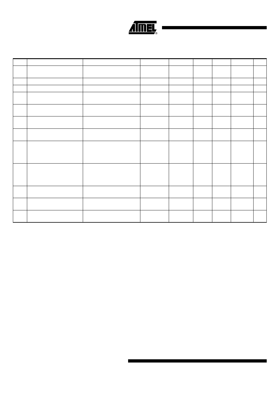
7.
Electrical Characteristics (Continued)
If no additional information is given in column Test Conditions, the values apply to a temperature range from –40°C to +85°C.
No.
Parameters
Test Conditions
Pin
Symbol
Min.
Typ.
Max.
Unit
Notes:
1. VDDIO is the supply voltage for the following GPIO pins: P1, P2, P8, P12, P14, P16, P17, P18, P19, P20, P21, P23, P24,
P25, P26, P27 and P29
2. Values defined for operating the USB interface. Otherwise VDD_USB may be connected to ground
3. Supply voltage VBAT18 for backup domain is generated internally by the LDOBAT