Rainbow Electronics DS1629 User Manual
Page 9
DS1629
9 of 22
102299
DS1629 SRAM FORMAT Table 4
BYTE
CONTENTS
00h
SRAM BYTE 0
01h
SRAM BYTE 1
02h
SRAM BYTE 2
•
•
•
•
•
•
1Eh
SRAM BYTE 30
1Fh
SRAM BYTE 31
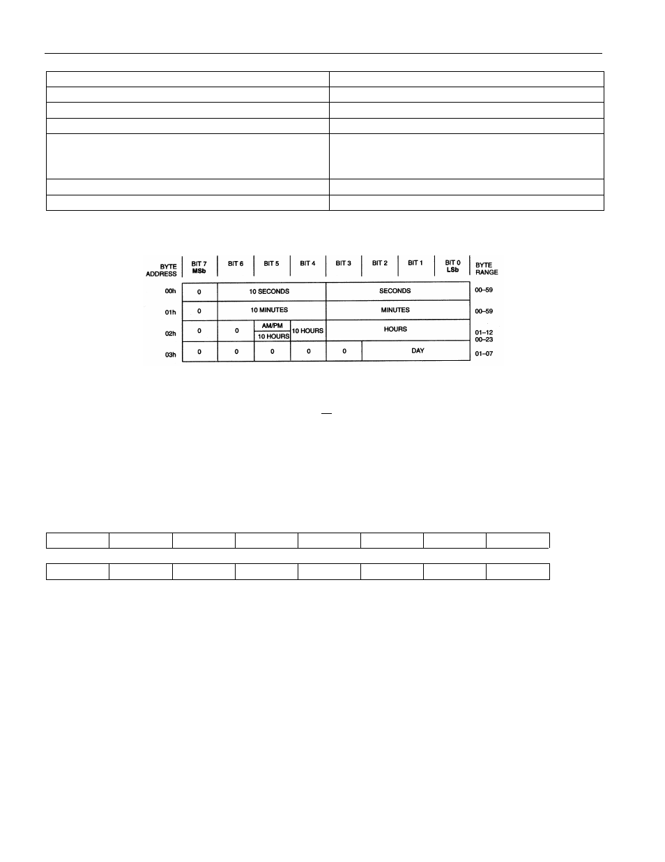
DS1629 CLOCK ALARM REGISTER FORMAT Figure 4
OPERATION-Configuration/Status Register
The configuration/status register is accessed via the Access Config (ACh) function command. Writing to
or reading from the register is determined by the R/
W
bit of the 2-wire control byte (See “2-Wire Serial
Data Bus” section). Data is read from or written to the configuration register MSb first. The format of the
register is illustrated in Figure 5. The effect each bit has on DS1629 functionality is described along with
the power-up state and volatility. The user has read/write access to the MSB and read-only access to the
LSB of the register.
Configuration/Status Register Figure 5
OS1
OS0
A1
A0
0
CNV
POL
1SH
MSB
MSb
LSb
CAF
TAF
CAL
TAL
0
0
0
0
LSB
1SH = Temperature Conversion Mode. If 1SHOT is "1", the DS1629 will perform one temperature
conversion upon reception of the Start Convert T protocol. If 1SHOT is "0", the DS1629 will
continuously perform temperature conversions and store the last completed result in the Thermometer
Register. The user has read/ write access to the nonvolatile bit, and the factory default state is "0"
(continuous mode).
POL = ALRM Polarity Bit. If POL = "1", the active state of the ALRM output will be high. A "0" stored
in this location sets the thermostat output to an active low state. The user has read/write access to the
nonvolatile POL bit, and the factory default state is "0" (active low).
CNV = Power-up conversion state. If CNV="0" (factory default), the DS1629 will automatically initiate a
temperature conversion upon power-up and supply stability. Setting CNV="1" will cause the DS1629 to
power-up in a standby state. Table 5 illustrates how the user can set 1SH and CNV, depending on the
power consumption sensitivity of the application.