Thermometer alarm, Thermostat setpoint (th/tl) format table 3, Clock alarm – Rainbow Electronics DS1629 User Manual
Page 8: Operation-user sram
DS1629
8 of 22
102299
Thermometer Alarm
The thermostat comparator updates as soon as a temperature conversion is complete. When the DS1629’s
temperature meets or exceeds the value stored in the high temperature trip register (TH), the TAF flag
becomes active (high), and will stay active until the temperature falls below the temperature stored in the
low temperature trigger register (TL).
The respective register can be accessed over the 2-wire bus via the Access TH (A1h) or Access TL (A2h)
commands. Reading from or writing to the respective register is controlled by the state of the R/
W
bit in
the 2-wire control byte (See “2-wire Serial Data Bus” section).
The format of the TH and TL registers is identical to that of the Thermometer register; that is, 9-bit 2’s
complement representation of the temperature in °C. Both TH and TL are nonvolatile EEPROM registers
guaranteed to 2K write cycles.
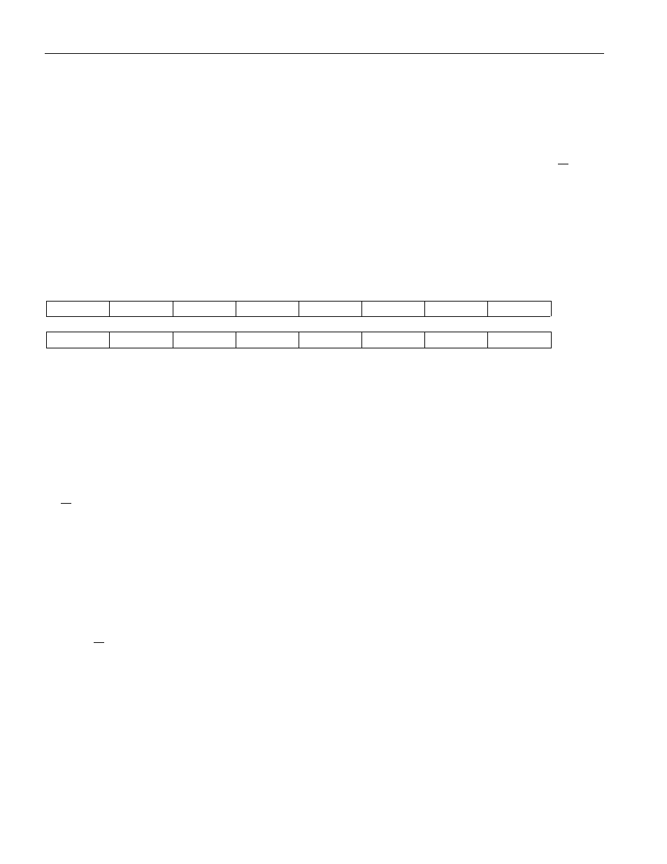
Thermostat Setpoint (TH/TL) Format Table 3
S
2
6
2
5
2
4
2
3
2
2
2
1
2
0
MSB
MSb
(unit = °C)
LSb
2
-1
0
0
0
0
0
0
0
LSB
Clock Alarm
The clock alarm flag (CAF) becomes active within one second after the second, minute, hour, and day (of
the week) of the clock register match the respective bytes in the clock alarm register. CAF will remain
active until the bus master writes to or reads from either the clock register via the C0h command or the
clock alarm register via the C7h command.
The format of the clock alarm register is shown in Figure 4. The power-up default of the DS1629 has the
clock alarm set to 12:00AM on Sunday. The register can be accessed over the 2-wire bus via the Access
Clock Alarm (C7h) command. Reading from or writing to the register is controlled by the state of the
R/
W
bit in the 2-wire control byte (See “2-wire Serial Data Bus” section).
The master must take precaution in programming bit 5 of byte 02h to ensure that the alarm setting
matches the current clock mode. Bits designated with a 0 are a "don't care" on writes, but will always read
out as a 0.
OPERATION-USER SRAM
The DS1629 has memory reserved for any purpose the user intends. The page is organized as 32 bytewide
locations. The SRAM space is formatted as shown in Table 4. It is accessed via the 2-wire protocol 17h.
If the R/
W
bit of the control byte is set to 1, the SRAM will be read and a 0 in this location allows the
master to write to the array. Reads or writes can be performed in the single byte or page mode. As such,
the master must write the byte address of the first data location to be accessed.
If the bus master is writing to/reading from the SRAM array in the page mode (multiple byte mode), the
address pointer will automatically wrap from address 1Fh to 00h following the ACK after byte 1Fh.
The SRAM array does not have a defined power-up default state. Refer to the “Command Set” section for
details of the Access Memory protocol.