Temperature/data relationships table 2 – Rainbow Electronics DS1629 User Manual
Page 5
DS1629
5 of 22
102299
At the same time, the counter is then preset with a value determined by the slope accumulator circuitry.
This circuitry is needed to compensate for the parabolic behavior of the oscillators over temperature. The
counter is then clocked again until it reaches 0. If the gate period is still not finished, then this process
repeats.
The slope accumulator is used to compensate for the nonlinear behavior of the oscillators over
temperature, yielding a high resolution temperature measurement. This is done by changing the number
of counts necessary for the counter to go through for each incremental degree in temperature. To obtain
the desired resolution, therefore, both the value of the counter and the number of counts per degree C (the
value of the slope accumulator) at a given temperature must be known.
Internally, this calculation is done inside the DS1629 to provide 0.5
°
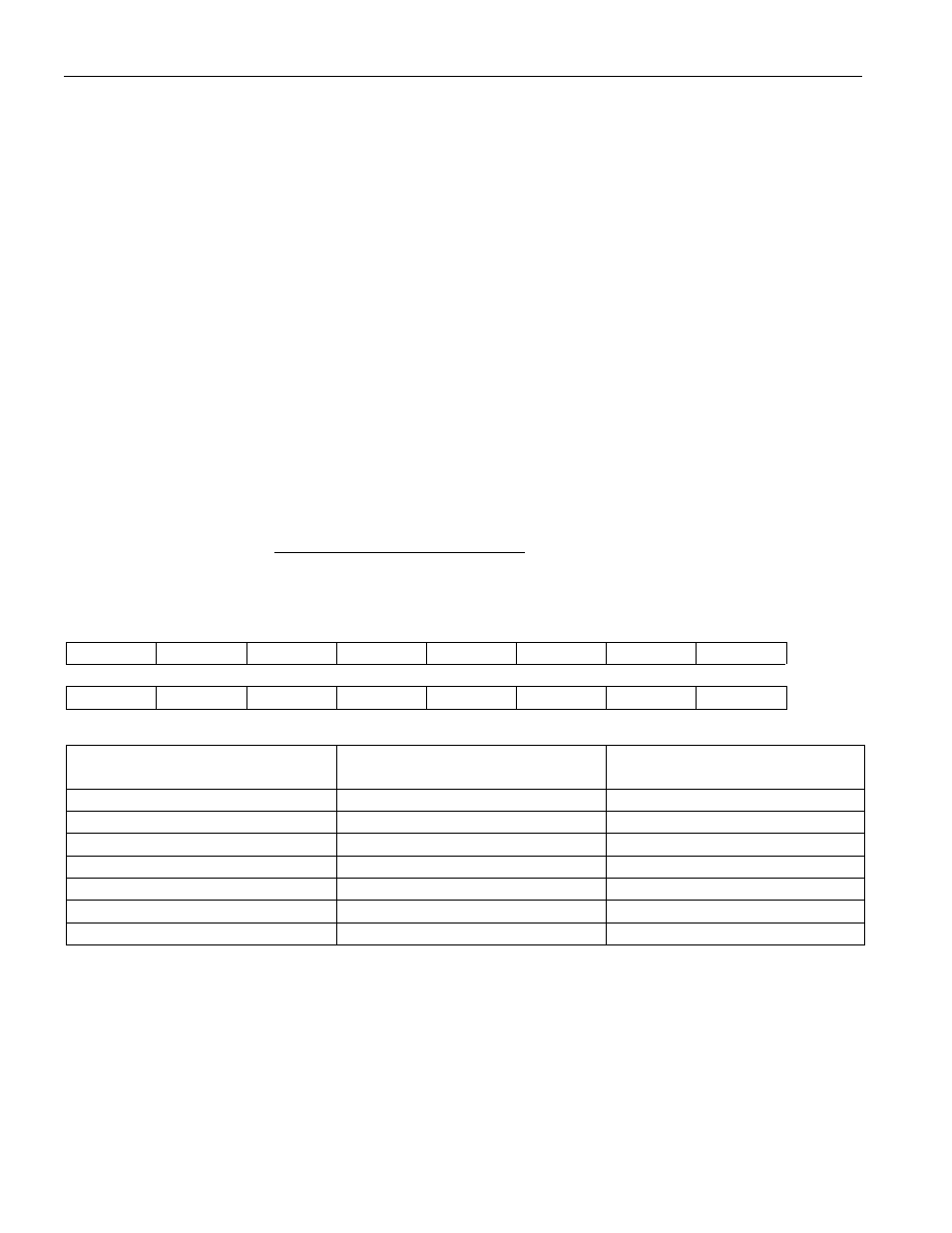
C resolution. Table 2 describes the
exact relationship of output data to measured temperature. For Fahrenheit usage, a lookup table or
conversion factor must be used.
Note that temperature is represented in the DS1629 in terms of a 0.5
°
C LSB, yielding the 9-bit format
illustrated in Table 2. Higher resolutions may be obtained by implementing the algorithm in Application
Note 105 and performing the following calculation. The 8-bit COUNT_REMAIN value can be obtained
via the Read Counter (A8h) command and the COUNT_PER_C value (also 8-bit) is read via the Read
Slope command (A9h).
T = TEMP_READ -0.25 +
C
COUNT_PER_
EMAIN)
_C_COUNT_R
(COUNT_PER
Temperature/Data Relationships Table 2
S
2
6
2
5
2
4
2
3
2
2
2
1
2
0
MSB
MSb
(unit = °C)
LSb
2
-1
0
0
0
0
0
0
0
LSB
TEMPERATURE
DIGITAL OUTPUT
(Binary)
DIGITAL OUTPUT
(Hex)
+125°C
01111101 00000000
7D00h
+25°C
00011001 00000000
1900
0.5°C
00000000 10000000
0080
0°C
00000000 00000000
0000
-0.5°C
11111111 10000000
FF80
-25°C
11100111 00000000
E700h
-55°C
11001001 00000000
C900h