Rainbow Electronics DS1629 User Manual
Page 6
DS1629
6 of 22
102299
OPERATION-Real Time Clock/Calendar
DS1629 real-time clock/calendar data is accessed with the 2-wire command protocol C0h. If the R/
W
bit
in the 2-wire control byte is set to 0, the bus master will set the clock (write to the clock register). The bus
master sets the R/
W
bit to 1 to read the current time (read from the clock register). Refer to the “2-Wire
Serial Bus” section for details on this protocol.
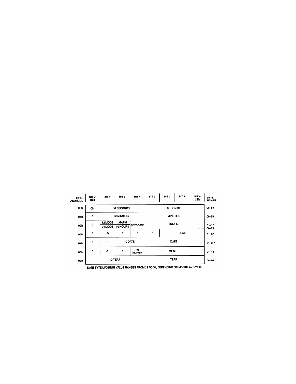
The format of the clock register is shown below in Figure 2. Data format for the clock register is binary-
coded decimal (BCD). Most of the clock register is self-explanatory, but a few of the bits require
elaboration.
CH = Clock halt bit. This bit is set to 0 to enable the oscillator and set to 1 to disable it. If the bit is
changed during a write to the clock register, the oscillator will not be started (or stopped) until the bus
master issues a STOP pulse. The DS1629 power-up default has the oscillator enabled (CH=0) so that
OSC can be used for clocking a microcontroller at power-up.
12/24 = Clock mode bit. This bit is set high when the clock is in the 12-hour mode and set to 0 in the 24-
hour mode. Bit 5 of byte 02h of the clock register contains the MSb of the hours (1 for hours 20-23) if the
clock is in the 24-hour mode. If the clock mode is set to the 12-hour mode, this is the AM/PM bit. In the
12-hour mode, a 0 in this location denotes AM and a 1 denotes PM. When setting the clock, this bit must
be written to according to the clock mode used.
Bits in the clock register filled with 0 are a "don't care" on a write, but will always read out as 0.
DS1629 CLOCK REGISTER FORMAT Figure 2