Recommended layout for crystal – Rainbow Electronics DS1678 User Manual
Page 5
DS1678
5 of 26
INT
(Interrupt Input/Output) – The
INT
pin is an I/O that will be activated by an external device to
signify an event has occurred and should be logged. Once the pin is activated, the event will be recorded
in the event log memory and the event counter register will be incremented by one.
The
INT
pin can be activated in three different ways depending on how the user programs the TRx bits.
The event can be triggered by a falling edge on the
INT
pin only, a rising edge only, or it can be
triggered by both the rising and falling edges. By logging both the rising and falling edges as events, the
time when something is turned on and turned off can be determined and the amount of time that the
external system was in either state.
This assumes that the external system always starts logging data in a known state. For example, if a light
switch is being monitored and the switch is always in the off position before a mission is started, the first
event would be turning the lights on. The next event would have to be to turn the lights off. The time
between the events would be the amount of time the lights were in the on state. The time from turning the
lights off until the next event, which would be to turn the lights back on again, would be the amount of
time the lights were off.
The
INT
pin can also be used as an output when the DS1678 is not in an event logging mission. The
INT
pin will become an output and generate an alarm interrupt if the DISx bits are both set to zero and the
RTC reaches the preset value in the alarm register. The
INT
output remains low as long as the status bit
causing the interrupt is present and the DISx bits are both set to zero.
The
INT
pin is an open-drain input/output with a weak internal pull-down resistor to prevent the pin
from floating if the signal connected to the pin is tri-stated. Without the resistor, the input would float
and potentially log phantom events. With the pull-down resistor, the pin can be transitioned to a low state
causing an event to be recorded if the
INT
pin was being held high by an outside signal that becomes tri-
stated.
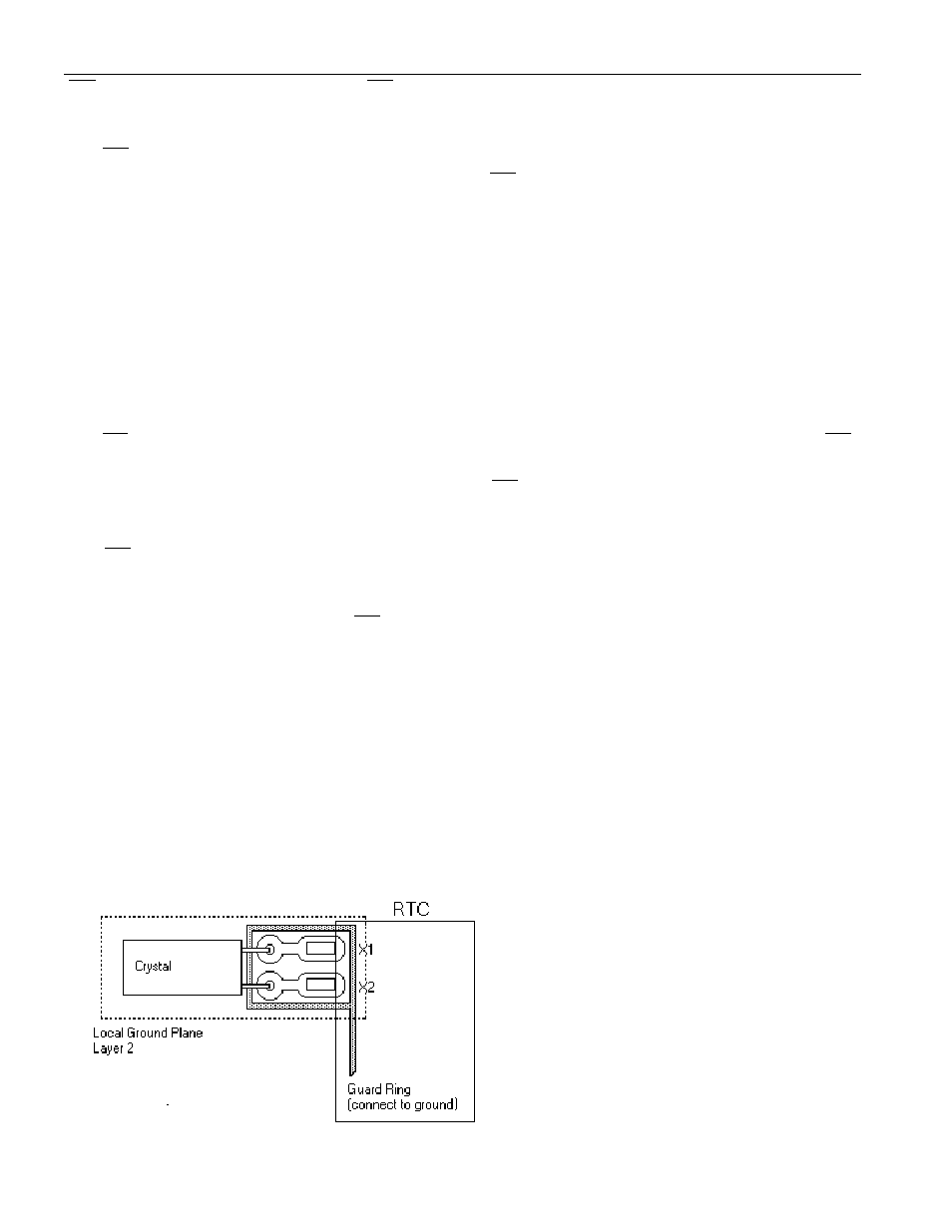
X1, X2 – Connections for a standard 32.768kHz quartz crystal, Daiwa part number DT-26S or
equivalent. For greatest accuracy, the DS1678 must be used with a crystal that has a specified load
capacitance of 12.5pF. There is no need for external capacitors or resistors. Note: X1 and X2 are very
high impedance nodes. It is recommended that they and the crystal be guard-ringed with ground and that
high frequency signals be kept away from the crystal area. For more information on crystal selection and
crystal layout considerations, please consult Application Note 58, “Crystal Considerations with Dallas
Real-Time Clocks.”
RECOMMENDED LAYOUT FOR CRYSTAL