Rainbow Electronics HD44780 User Manual
Page 55
HD44780U
55
6. Applies to input pins and I/O pins, excluding the OSC1 pin.
7. Applies to I/O pins.
8. Applies to output pins.
9. Current flowing through pull–up MOSs, excluding output drive MOSs.
10. Input/output current is excluded. When input is at an intermediate level with CMOS, the excessive
current flows through the input circuit to the power supply. To avoid this from happening, the input
level must be fixed high or low.
11. Applies only to external clock operation.
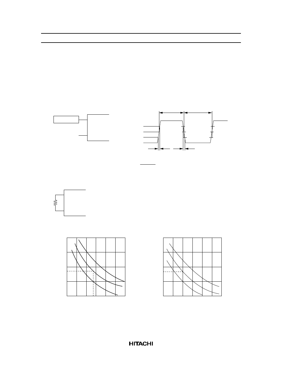
Oscillator
OSC1
OSC2
0.7 V
CC
0.5 V
CC
0.3 V
CC
Th
Tl
t
rcp
t
fcp
Duty = 100%
Th
Th + Tl
×
Open
12. Applies only to the internal oscillator operation using oscillation resistor R
f
.
OSC1
OSC2
R
f
R :
R :
f
f
75 k
±
2% (when V
CC
= 3 V)
91 k
±
2% (when V
CC
= 5 V)
Ω
500
400
300
200
100
50
100
150
(91)
R (k )
f
Ω
f (kHz)
OSC
V
CC
= 5 V
500
400
300
200
100
50
100
150
R (k )
f
Ω
f (kHz)
OSC
V
CC
= 3 V
typ.
Since the oscillation frequency varies depending on the OSC1 and
OSC2 pin capacitance, the wiring length to these pins should be minimized.
(270)
(270)
Ω
(75)
typ.
max.
min.
max.
min.