Rainbow Electronics HD44780 User Manual
Page 25
HD44780U
25
Table 6
Instructions (cont)
Code
Execution Time
(max) (when f
cp
or
Instruction RS
R/
W
DB7 DB6 DB5 DB4 DB3 DB2 DB1 DB0 Description
f
OSC
is 270 kHz)
Write data
to CG or
DDRAM
1
0
Write data
Writes data into DDRAM or
CGRAM.
37
µ
s
t
ADD
= 4
µ
s*
Read data
from CG or
DDRAM
1
1
Read data
Reads data from DDRAM or
CGRAM.
37
µ
s
t
ADD
= 4
µ
s*
I/D
= 1:
Increment
I/D
= 0:
Decrement
S
= 1:
Accompanies display shift
S/C = 1: Display shift
S/C = 0:
Cursor move
R/L = 1:
Shift to the right
R/L = 0:
Shift to the left
DL
= 1:
8 bits, DL = 0: 4 bits
N
= 1:
2 lines, N = 0: 1 line
F
= 1:
5
×
10 dots, F = 0: 5
×
8 dots
BF
= 1:
Internally operating
BF
= 0: Instructions acceptable
DDRAM: Display data RAM
CGRAM: Character generator
RAM
ACG:
CGRAM address
ADD:
DDRAM address
(corresponds to cursor
address)
AC: Address counter used for
both DD and CGRAM
addresses
Execution time
changes when
frequency changes
Example:
When f
cp
or f
OSC
is
250 kHz,
37
µ
s
×
= 40
µ
s
270
250
Note:
— indicates no effect.
*
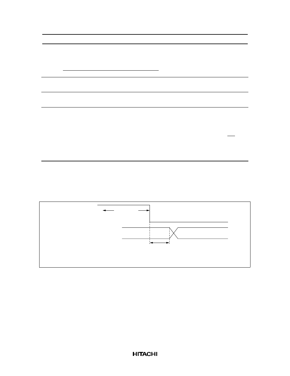
After execution of the CGRAM/DDRAM data write or read instruction, the RAM address counter
is incremented or decremented by 1. The RAM address counter is updated after the busy flag
turns off. In Figure 10, t
ADD
is the time elapsed after the busy flag turns off until the address
counter is updated.
Busy state
Busy signal
(DB7 pin)
Address counter
(DB0 to DB6 pins)
t
ADD
A
A + 1
Note: t depends on the operation frequency
t = 1.5/(f or f ) seconds
ADD
ADD
cp
OSC
Figure 10 Address Counter Update