Output load – Rainbow Electronics DS1384 User Manual
Page 16
DS1384
16 of 17
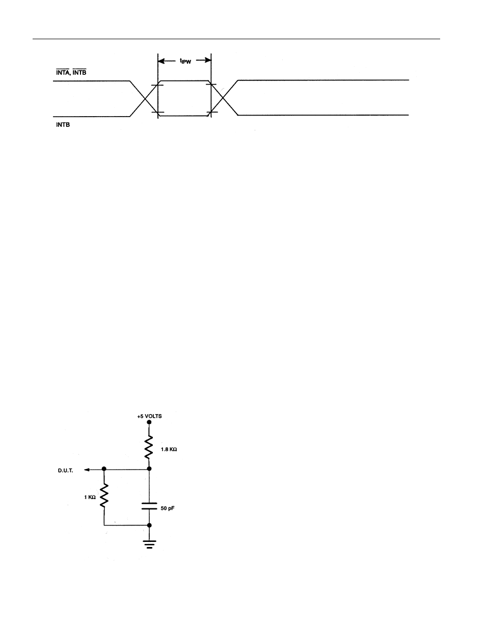
TIMING DIAGRAM: INTERRUPT OUTPUTS PULSE MODE (SEE NOTES 8, 9)
NOTES:
1. All voltages are referenced to ground.
2. Typical values are at 25
°
C and nominal supplies.
3. Outputs are open.
4. Value for voltage and currents is from the V
CCI
input pin to the V
CCO
pin.
5. Write protection trip point occurs during power fail prior to switchover from V
CC
to V
BAT
.
6. Value for voltage and currents is from the V
BAT
input pin to the V
CCO
pin.
7. Data retention time depends on the size of battery selected and the amount of current demanded by
the static RAM in back-up mode. The battery capacity (mA
•
=hr) to achieve a T
DR
of 10 years is given
by the formula: C=(I
BAT1
+ I
RAM
) x 24 x 365 x 10, where I
RAM
is the standby current of the static
RAM at the battery voltage. For the DS1384 chip alone, a standard 48 mAh lithium cell battery will
provide greater than 10 years of data retention in the absence of power.
8. Applies to both interrupt pins when the alarms are set to pulse.
9. Interrupt output occurs within 100 ns of the alarm condition existing.
OUTPUT LOAD