External sram chip enable table 3 – Rainbow Electronics DS1670 User Manual
Page 8
DS1670
8 of 17
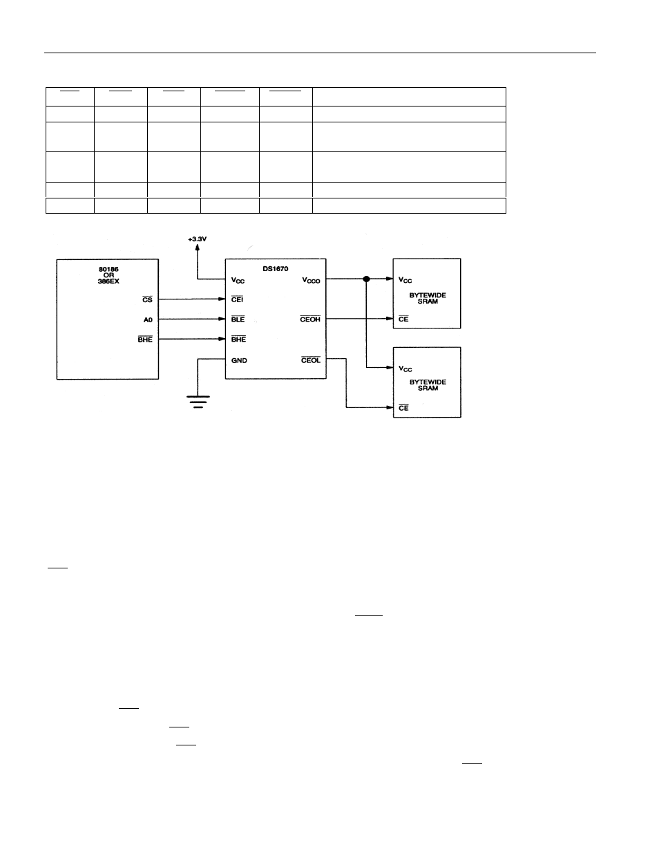
EXTERNAL SRAM CHIP ENABLE Table 3
CEI
BHE
BLE
CEOL
CEOH
FUNCTION
0
0
0
0
0
Word Transfer
0
0
1
1
0
Byte Transfer in upper half of data
bus (D15-D8)
0
1
0
0
1
Byte Transfer in lower half of data
bus (D7-D0)
0
1
1
1
1
External SRAMs disabled
1
X
X
1
1
External SRAMs disabled
EXTERNAL SRAM INTERFACE (WORD-WIDE) TO THE DS1670 Figure 4
MICROPROCESSOR MONITOR
The DS1670 monitors three vital conditions for a microprocessor: power supply, software execution, and
external override.
First, a precision temperature-compensated reference and comparator circuit monitors the status of V
CC
.
When an out-of-tolerance condition occurs, an internal power-fail signal is generated which forces the
RST
pin to the active state, thus warning a processor-based system of impending power failure. The
power-fail trip point is 2.88 volts (typical). When V
CC
returns to an in-tolerance condition upon power-
up, the reset signal is kept in the active state for 250 ms (typical) to allow the power supply and
microprocessor to stabilize. Note, however, that if the
EOSC
bit is set to a logic 1 (to disable the
oscillator during battery back-up mode), the reset signal will be kept in an active state for 250 ms plus the
start-up time of the oscillator.
The second monitoring function is pushbutton reset control. The DS1670 provides for a pushbutton
switch to be connected to the RST output pin. When the DS1670 is not in a reset cycle, it continuously
monitors the
RST
signal for a low-going edge. If an edge is detected, the DS1670 will debounce the
switch by pulling the
RST
line low. After the internal 250 ms timer has expired, the DS1670 will
continue to monitor the
RST
line. If the line is still low, the DS1670 will continue to monitor the line
looking for a rising edge. Upon detecting release, the DS1670 will force the
RST
line low and hold it
low for 250 ms.