Ds1094l multiphase spread-spectrum econoscillator, Table 3. phase generator settings, Table 4. dither amount settings – Rainbow Electronics DS1094L User Manual
Page 7: Table 5. dither frequency settings
Prescaler
The prescaler divides the master oscillator frequency,
f
MOSC
, by 1, 2, 4, or 8. The resultant frequency, f
OSC
, is
calculated using the following formula:
f
OSC
= f
MOSC
/ 2
PRESCALER
where PRESCALER can be 0 to 3. The prescaler is con-
figured using bits P1 and P0 in the PRESCALER regis-
ter. Valid settings are shown in Table 2. The location of
bits P1 and P0 in the PRESCALER register is shown in
the Control Registers section.
Note that the PRESCALER register also contains bits
controlling other features of the device (dither amount,
dither rate, and phase).
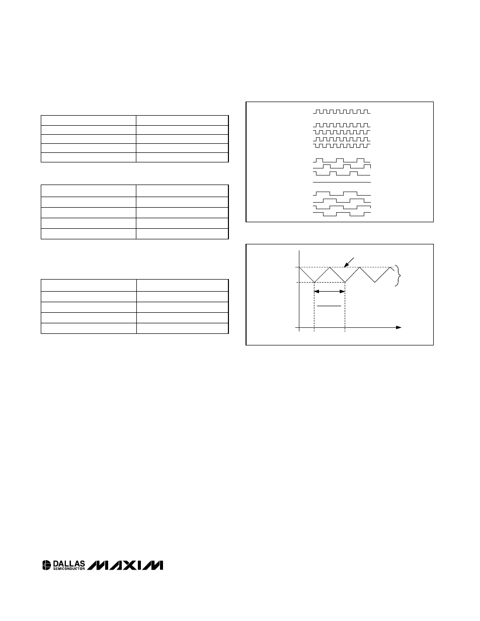
Phase Generator
The four oscillator outputs (OUT1 to OUT4) can be con-
figured in either two-phase, three-phase, or four-phase
mode. The output waveforms of each mode are illus-
trated in Figure 1. Likewise, the figure also shows a
comparison of f
OUT
, the duty cycle, and the output
phase shifts between the three modes. Bits Ph1 and
Ph0 in the PRESCALER register are used to select the
desired mode (see Table 3). The location of bits Ph1
and Ph0 in the PRESCALER register is shown in the
Control Registers section.
Triangle Wave Generator
The triangle wave generator is used to dither the mas-
ter oscillator frequency, adding spread-spectrum func-
tionality to the DS1094L by injecting an offset element
into the master oscillator. Both the dither amount (%)
and dither frequency are programmable. The dither
amount is controlled by bits J1 and J0 in the
PRESCALER register. The dither frequency is con-
trolled by bits D1 and D0, also in the PRESCALER reg-
ister. The bit settings are shown in Table 4 and 5. The
location of bits J1, J0, D1, and D0 in the PRESCALER
register is shown in the Control Registers section.
When dither is enabled (by selecting a percentage
other than 0%), the master oscillator frequency, f
MOSC
,
is dithered between the programmed f
MOSC
and the
selected percentage down from the programmed
f
MOSC
(see Figure 2). For example, if f
MOSC
is pro-
grammed to 2MHz (DAC register = 0Ah) and the dither
amount is programmed to 2%, the frequency of f
MOSC
DS1094L
Multiphase Spread-Spectrum EconOscillator
_____________________________________________________________________
7
BITS Ph1, Ph0
MODE
00
Two-Phase
01
Three-Phase
10
Four-Phase
11
Reserved
Table 3. Phase Generator Settings
BITS J1, J0
DITHER AMOUNT*
00
0%
01
2%
10
4%
11
8%
Table 4. Dither Amount Settings
BITS D1, D0
DITHER FREQUENCY
00
f
MOSC
/128
01
f
MOSC
/256
10
f
MOSC
/512
11
f
MOSC
/1024
Table 5. Dither Frequency Settings
OUT1
OUT2
OUT3
OUT4
OUT1
OUT2
OUT3
OUT4
OUT1
OUT2
OUT3
OUT4
f
OSC
TWO-PHASE
THREE-PHASE
FOUR-PHASE
50% DUTY CYCLE
50% DUTY CYCLE
33% DUTY CYCLE
120 DEGREES
OUT OF PHASE
180 DEGREES
90 DEGREES OUT
OF PHASE
f
OUT
= f
OSC
OUT OF PHASE
f
OUT
= f
OSC
/ 3
f
OUT
= f
OSC
/ 4
Figure 1. DS1094L Output Waveforms
TIME
1
DITHER FREQ.
PROGRAMMED f
MOSC
PROGRAMMED f
MOSC
-
(2, 4, OR 8% OF f
MOSC
)
DITHER
AMOUNT
(2, 4, OR 8%)
IF DITHER AMOUNT = 0%
f
MOSC
Figure 2. DS1094L Dither Waveform
*The frequency is dithered down from the programmed value
of f
MOSC
.