Atr0600 [preliminary, Absolute maximum ratings, Thermal resistance – Rainbow Electronics ATR0600 User Manual
Page 4: Recommended operating conditions, Electrical characteristics
4
ATR0600 [Preliminary]
4536F–GPS–10/03
.
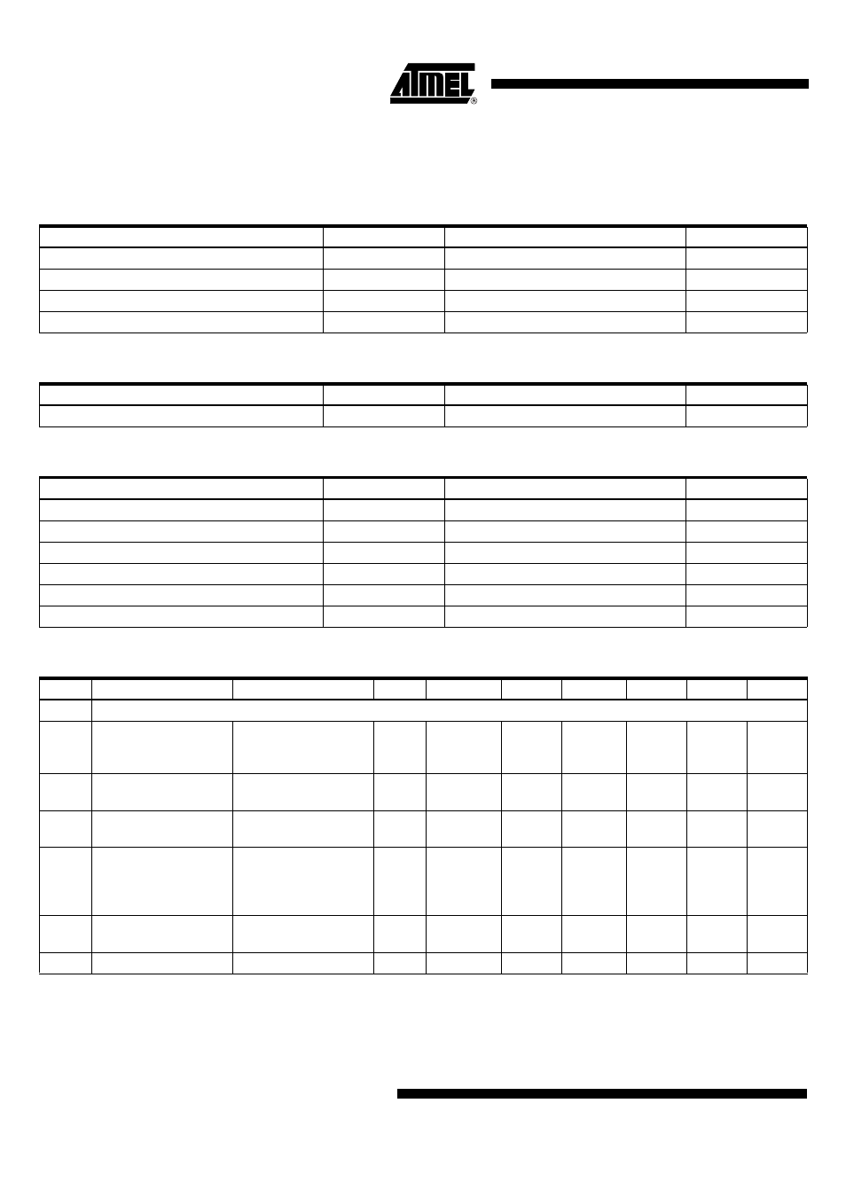
Absolute Maximum Ratings
Stresses beyond those listed under “Absolute Maximum Ratings” may cause permanent damage to the device. This is a stress rating
only and functional operation of the device at these or any other conditions beyond those indicated in the operational sections of this
specification is not implied. Exposure to absolute maximum rating conditions for extended periods may affect device reliability.
Parameters
Symbol
Value
Unit
Supply voltage
V
S
3.7
V
Input voltage
V
in
3.7
V
Junction temperature
T
j
125
°C
Storage temperature range
T
stg
-40 to +125
°C
Thermal Resistance
Parameters
Symbol
Value
Unit
Junction ambient
R
thJA
125
K/W
Recommended Operating Conditions
Parameters
Symbol
Value
Unit
Supply voltage
V
S
2.7 to 3.3
V
Temperature range
Temp
-40 to +85
°C
Input frequency
f
in, mixer
1575.42
MHz
Reference frequency
f
ref
23.104
MHz
External IF filter (see Figure 13 on page 9)
Supply voltage digital interface, pin 27
V
DD
1.65 to 2.0
V
Electrical Characteristics
No.
Parameters
Test Conditions
Pin
Symbol
Min.
Typ.
Max.
Unit
Type*
1
Common
1.1
Supply current
P1 = P2 = VPU
on
3, 6,
11,
19, 23
I
S
18
mA
A
1.2
Supply current XTO
P1 = VPU
off
P2 = VPU
on
6
I
XTO
2
mA
A
1.3
Supply current digital
interface
P1 = P2 = VPU
on
27
I
DD
250
µA
A
1.4
Supply current (power
down)
P1 = P2 = VPU
OFF
3, 6,
11,
19,
23, 27
I
S, pd
20
µA
A
1.5
Total gain
RFIN, RNIN matched,
to 50
W
, V
GC
= 2.2 V
1
G
95
dB
B
1.6
Noise figure
N
F
6.9
dB
C
*) Type means: A = 100% tested, B = 100% correlation tested, C = Characterized on samples, D = Design parameter