Electrical characteristics (continued) – Rainbow Electronics DS2127 User Manual
Page 3
DS2127
Ultra3 LVD/SE SCSI 14-Line Terminator
_____________________________________________________________________
3
Note 1: All voltages are referenced to ground.
Note 2: Guaranteed by design and not production tested.
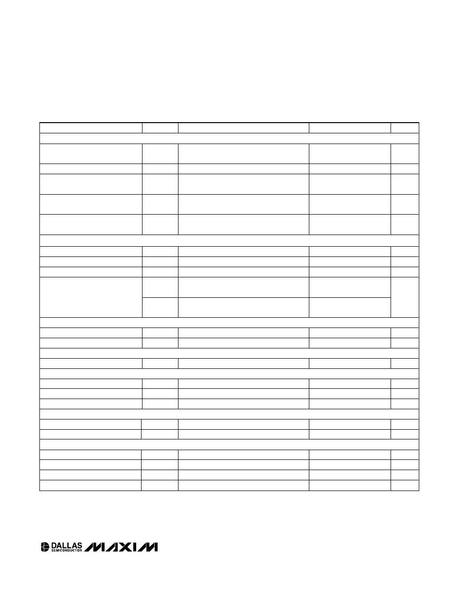
ELECTRICAL CHARACTERISTICS (continued)
(TPWR = V
TPWR(MIN)
to V
TPWR(MAX)
, T
A
= 0°C to +70°C, unless otherwise noted.)
PARAMETER
SYMBOL
CONDITIONS
MIN
TYP
MAX
UNITS
V
REF
REGULATOR
1.25V Regulator Line Regulation
V
REF
unloaded; vary TPWR from
2.7V to 5.5V
1.0
2.5
%
2.85V Regulator
2.7
2.85
3.0
V
2.85V Regulator Short-Circuit
Source Current
V
REF
= 0V
-375
-700
-1000
mA
2.85V Regulator Short-Circuit
Sink Current
V
REF
= 3.3V
170
300
700
mA
2.85V Regulator Line Regulation
V
REF
unloaded; vary TPWR from
2.7V to 5.5V
1.0
2.5
%
DIFFSENS OUTPUT
DIFFSENS Driver Output Voltage
V
DSO
-5mA
≤ I
DIFFSENS
≤ 50µA
1.2
1.4
V
DIFFSENS Driver Source Current
I
DSH
V
DIFFSENS
= 0V
-15
-5
mA
DIFFSENS Driver Sink Current
I
DSL
V
DIFFSENS
= 2.75V
100
200
µA
I
LEAK,
LOW
With ISO high, |V
DIFFSENS
| = 0.3V
-3
+1
DIFFSENS Leakage
I
LEAK,
HIGH
With ISO high, |V
DIFFSENS
- V
TPWR
| = 0.3V
1
3
µA
THERMAL SHUTDOWN
Thermal-Shutdown Threshold
For increasing temperature
130
°C
Thermal-Shutdown Hysteresis
10
°C
MODE CHANGE DELAY/FILTER
Mode Change Delay
t
DELAY
0.66
1.25
2.00
ms
LOGICAL SIGNALS (ISO)
Input Low Voltage
V
IL
-0.3
+0.8
V
Input High Voltage
V
IH
2.0
TPWR + 0.3
V
Input Current
I
IL
V
CC
= 3.3V
-30
-10
µA
STATUS BITS (LVD, SE)
Source Current
I
OH
V
CC
= 3.3V, V
LOAD
= 2.4V
-4
-6
mA
Sink Current
I
OL
V
CC
= 3.3V, V
LOAD
= 0.4V
2
5
mA
DIFF_CAP
Input Current
IL
V
IL
= -0.3V
-1
+1
µA
DIFF_CAP SE Operating Range
V
SEOR
-0.3
+0.5
V
DIFF_CAP LVD Operating Range
V
LVDOR
0.7
1.9
V
DIFF_CAP HVD Operating Range
V
HVDOR
2.4
V
TPWR
+ 0.3
V