Device operation – Rainbow Electronics CLC001 User Manual
Page 6
Device Operation
(Continued)
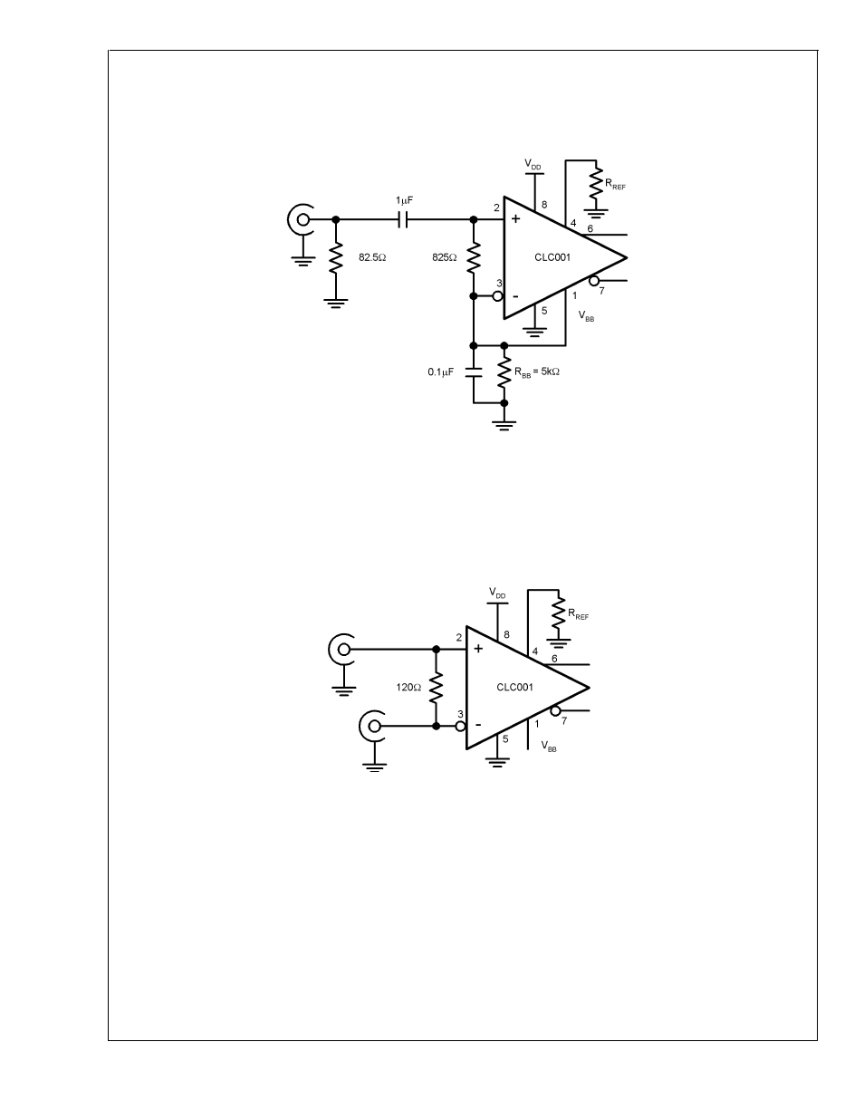
Figure 5 shows the CLC001 with an AC-coupled, single
ended input connection. The 82.5
Ω
resister in parallel
with 825
Ω
gives the equivalent termination resistance of
75
Ω
. R
BB
set at 5k
Ω
provides 1.25V of DC bias to the
input.
A typical DC-coupled, twisted pair cable connection is
shown in
Figure 6. The CLC001 is driven differentially.
The line is terminated with a termination resistor equal to
the impedance of the line being driven. The actual resistor
value is media specific, but typically is between 100 and
120
Ω
depending upon the cable. This resistor should be
located close to the CLC001 inputs pins to minimize the
resulting stub length between the resistor and device
pads.
DS101329-5
FIGURE 5. Single Ended 75
Ω
Coaxial Cable, AC-coupled
DS101329-6
FIGURE 6. Twisted Pair Cable, DC-coupled
CLC001
www.national.com
6
- MAX16840 (1 page)
- MAX9258 (54 pages)
- MAX66140 (21 pages)
- MAX9393 (14 pages)
- MAX66040 (25 pages)
- MAX6981 (1 page)
- MAX6965 (23 pages)
- MAX66100 (16 pages)
- MAX9135 (19 pages)
- MAX66020 (25 pages)
- MAX17127 (22 pages)
- MAX13175E (38 pages)
- MAX16820 (10 pages)
- MAX13237E (16 pages)
- MAX13483E (19 pages)
- MAX13362 (14 pages)
- MAX13486E (16 pages)
- MAX7311 (17 pages)
- MAX8759 (31 pages)
- SCAN92LV090 (13 pages)
- MAX6973 (23 pages)
- MAX13047E (14 pages)
- MAX16831 (20 pages)
- MAX14770E (15 pages)
- MAX11835 (1 page)
- MAX9621 (14 pages)
- MAX9217 (16 pages)
- MAX16841 (18 pages)
- MAX16834 (22 pages)
- MAX7315 (27 pages)
- MAX8645Y (15 pages)
- MAX6975 (23 pages)
- MAX6971 (12 pages)
- MAX3028 (21 pages)
- MAX9395 (13 pages)
- MAX7313 (27 pages)
- MAX6970 (1 page)
- MAX4821 (13 pages)
- MAX4895E (8 pages)
- MAX16823 (13 pages)
- MAX6963 (34 pages)
- MAX9216 (17 pages)
- MAX66000 (21 pages)
- MAX66120 (24 pages)
- MAX13223E (11 pages)