Test loads, Pin descriptions, Clc001 – Rainbow Electronics CLC001 User Manual
Page 4
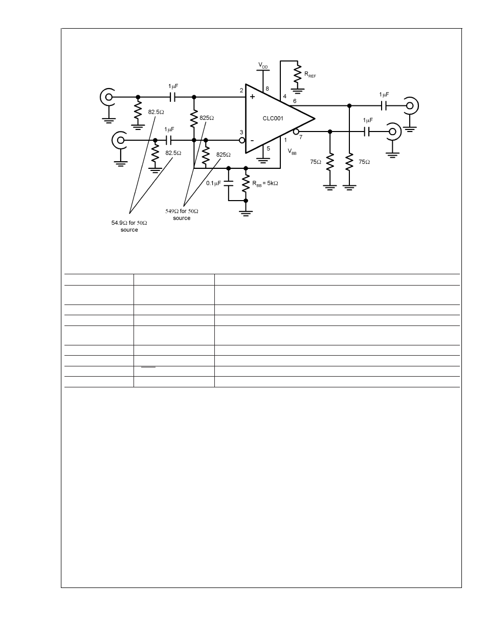
Test Loads
(Continued)
Pin Descriptions
Pin #
Name
Description
1
V
BB
Optional, bias voltage (may be used to bias inputs) - see device operation
section for details. If unused leave as no connect (NC).
2
V
IN+
Positive input pin
3
V
IN-
Negative input pin
4
R
REF
Output driver level control. Connect a resistor to ground to set output voltage
swing.
5
V
SS
Negative power supply
6
SDO
Serial data true output
7
SDO
Serial data complement output
8
V
DD
Positive power supply
DS101329-3
FIGURE 2. Test Circuit
CLC001
www.national.com
4
See also other documents in the category Rainbow Electronics Control panel:
- MAX16840 (1 page)
- MAX9258 (54 pages)
- MAX66140 (21 pages)
- MAX9393 (14 pages)
- MAX66040 (25 pages)
- MAX6981 (1 page)
- MAX6965 (23 pages)
- MAX66100 (16 pages)
- MAX9135 (19 pages)
- MAX66020 (25 pages)
- MAX17127 (22 pages)
- MAX13175E (38 pages)
- MAX16820 (10 pages)
- MAX13237E (16 pages)
- MAX13483E (19 pages)
- MAX13362 (14 pages)
- MAX13486E (16 pages)
- MAX7311 (17 pages)
- MAX8759 (31 pages)
- SCAN92LV090 (13 pages)
- MAX6973 (23 pages)
- MAX13047E (14 pages)
- MAX16831 (20 pages)
- MAX14770E (15 pages)
- MAX11835 (1 page)
- MAX9621 (14 pages)
- MAX9217 (16 pages)
- MAX16841 (18 pages)
- MAX16834 (22 pages)
- MAX7315 (27 pages)
- MAX8645Y (15 pages)
- MAX6975 (23 pages)
- MAX6971 (12 pages)
- MAX3028 (21 pages)
- MAX9395 (13 pages)
- MAX7313 (27 pages)
- MAX6970 (1 page)
- MAX4821 (13 pages)
- MAX4895E (8 pages)
- MAX16823 (13 pages)
- MAX6963 (34 pages)
- MAX9216 (17 pages)
- MAX66000 (21 pages)
- MAX66120 (24 pages)
- MAX13223E (11 pages)