Switched-capacitor voltage converters, Design information – Rainbow Electronics ICL7660 User Manual
Page 6
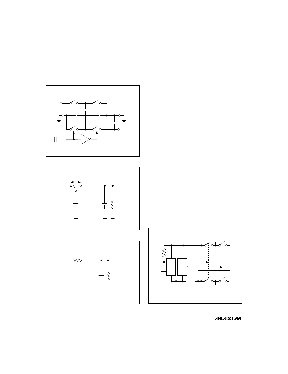
MAX1044/ICL7660
current is: I = f x
∆
Q = f x C1(V+ - V
OUT
). Rewriting this
equation in Ohm’s law form defines an equivalent resis-
tance synthesized by the switched-capacitor circuit
where:
where f is one-half the oscillator frequency. This resis-
tance is a major component of the output impedance of
switched-capacitor circuits like the MAX1044/ICL7660.
As shown in Figure 4, the MAX1044/ICL7660 contain
MOSFET switches, the necessary transistor drive cir-
cuitry, and a timing oscillator.
________________Design Information
The MAX1044/ICL7660 are designed to provide a
simple, compact, low-cost solution where negative or
doubled supply voltages are needed for a few low-
power components. Figure 5 shows the basic negative
voltage converter circuit. For many applications, only
two external capacitors are needed. The type of
capacitor used is not critical.
Proper Use of the Low-Voltage (LV) Pin
Figure 4 shows an internal voltage regulator inside the
MAX1044/ICL7660. Use the LV pin to bypass this
regulator, in order to improve low-voltage performance
I
(V+ - V
)
1 / (f x C1)
R
1
f x C1
OUT
EQUIV
=
=
and
Switched-Capacitor Voltage Converters
6
_______________________________________________________________________________________
S1
V+
S2
S3
S4
C1
C2
V
OUT
= -(V+)
Figure 2. Ideal Voltage Inverter
V+
C1
f
C2
R
LOAD
V
OUT
Figure 3a. Switched Capacitor Model
R
EQUIV
=
R
EQUIV
V
OUT
R
LOAD
1
V+
f
×
C1
C2
Figure 3b. Equivalent Circuit
1M
BOOST
pin 1
OSC
pin 7
LV
pin 6
GND
pin 3
CAP-
pin 4
S2
S1
S4
S3
CAP+
pin 2
V+
pin 8
V
OUT
pin 5
÷ 2
Q
OSCILLATOR
INTERNAL
REGULATOR
Q
Figure 4. MAX1044 and ICL7660 Functional Diagram