Applications information, Analog inputs – Rainbow Electronics MAX19507 User Manual
Page 31
MAX19507
Dual-Channel, 8-Bit, 130Msps ADC
______________________________________________________________________________________
31
Applications Information
Analog Inputs
Transformer-Coupled Differential Analog Input
The MAX19507 provides better SFDR and THD with
fully differential input signals than a single-ended input
drive. In differential input mode, even-order harmonics
are lower as both inputs are balanced, and each of the
ADC inputs only require half the signal swing compared
to single-ended input mode.
An RF transformer (Figure 18) provides an excellent
solution for converting a single-ended signal to a fully
differential signal. Connecting the center tap of the
transformer to CM_ provides a common-mode voltage.
The transformer shown has an impedance ratio of 1:1.4.
Alternatively, a different step-up transformer can be
selected to reduce the drive requirements. A reduced
signal swing from the input driver can also improve the
overall distortion. The configuration of Figure 18 is good
for frequencies up to Nyquist (f
CLK
/2).
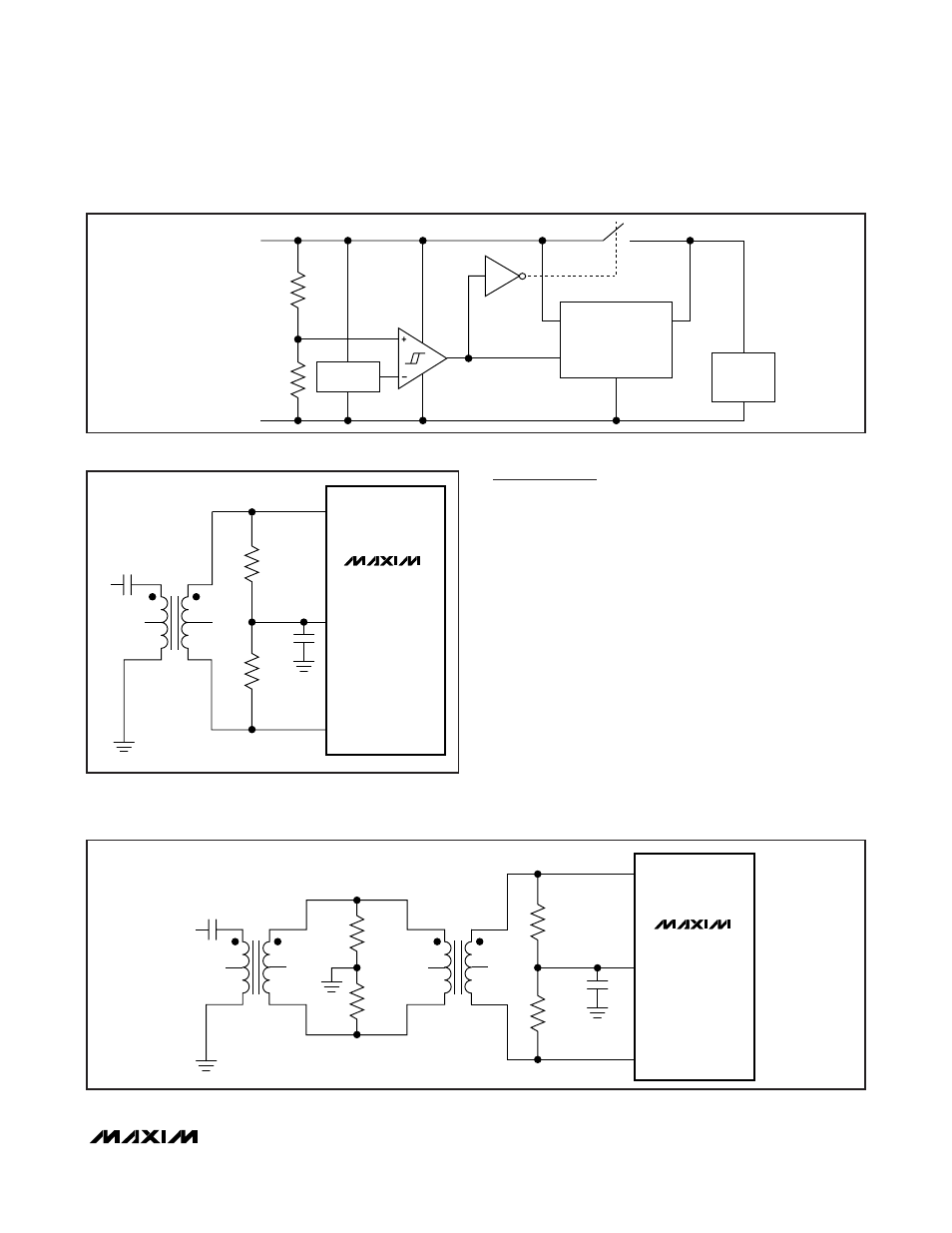
Figure 17. Integrated Voltage Regulator
IN
2.3V TO 3.5V
ENABLE
OUT
1.8V
REGULATOR
REFERENCE
INTERNAL
ANALOG
CIRCUITS
AVDD
(PINS 1, 12, 13, 48)
GND
Figure 19. Transformer-Coupled Input Drive for Input Frequencies Beyond Nyquist
1
5
3
6
2
4
N.C.
V
IN
0.1µF
T1
MINI-CIRCUITS
ADT1-1WT
IN_+
CM_
IN_-
N.C.
1
5
3
6
2
4
N.C.
T2
MINI-CIRCUITS
ADT1-1WT
N.C.
75Ω
0.5%
75Ω
0.5%
110Ω
0.5%
110Ω
0.5%
0.1µF
MAX19507
Figure 18. Transformer-Coupled Input Drive for Input
Frequencies Up to Nyquist
MAX19507
1
5
3
6
2
4
N.C.
N.C.
V
IN
0.1
µF
T1
MINI-CIRCUITS
ADT1-1WT
36.5
Ω
0.5%
36.5
Ω
0.5%
0.1
µF
IN_+
CM_
IN_-