Clock inputs, Clock divider – Rainbow Electronics MAX19507 User Manual
Page 24
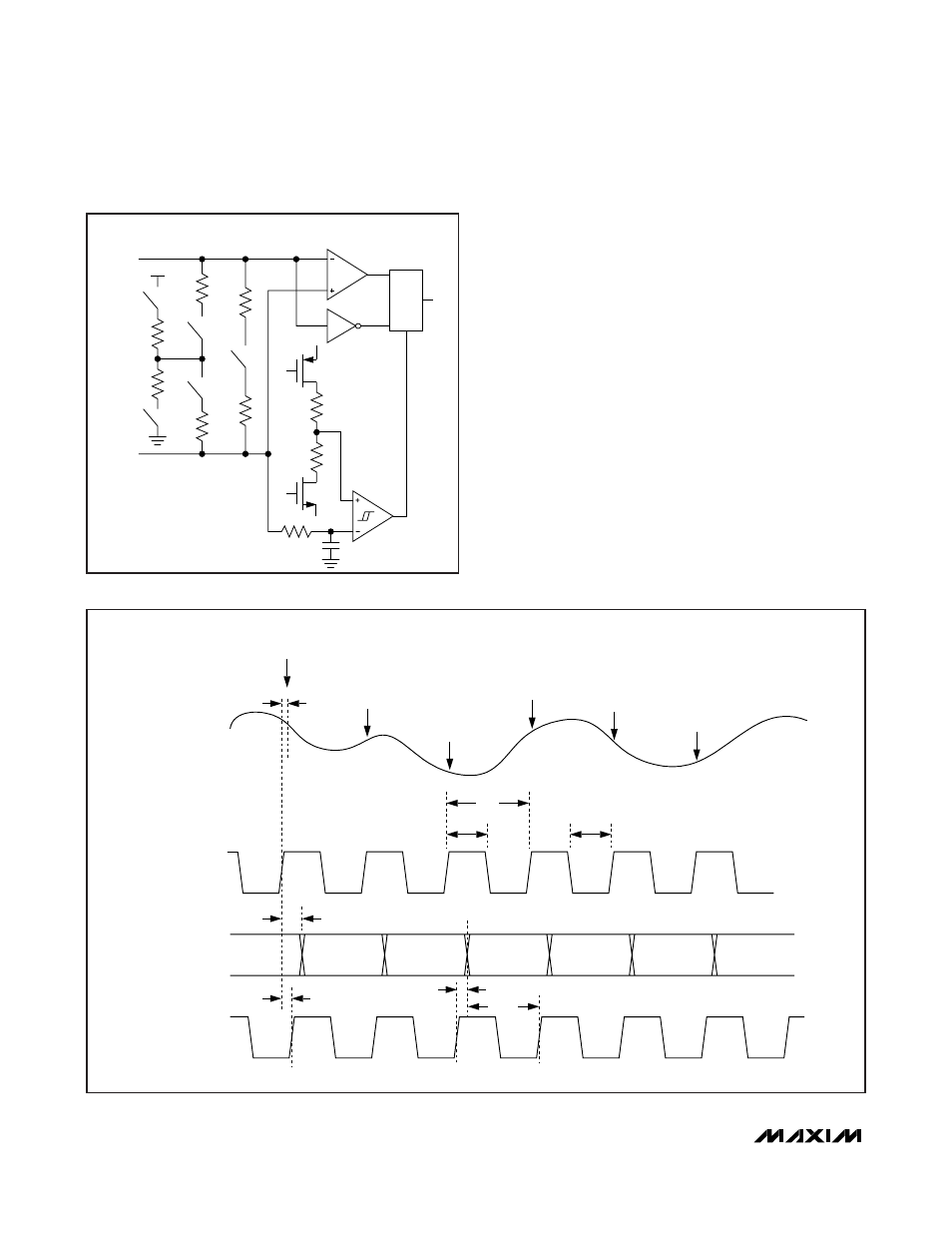
Clock Inputs
The input clock interface provides for flexibility in the
requirements of the clock driver. The MAX19507 accepts
a fully differential clock or single-ended logic-level clock.
For differential clock operation, connect a differential
clock to the CLK+ and CLK- inputs. In this mode, the
input common mode is established internally to allow for
AC-coupling. The differential clock signal can also be
DC-coupled if the common mode is constrained to the
specified 1V to 1.4V clock input common-mode range.
For single-ended operation, connect CLK- to GND and
drive the CLK+ input with a logic-level signal. When the
CLK- input is grounded (or pulled below the threshold of
the clock mode detection comparator) the differential-to-
single-ended conversion stage is disabled and the logic-
level inverter path is activated.
Clock Divider
The MAX19507 offers a clock-divider option. Enable
clock division either by setting DIV0 and DIV1 through
the serial interface; see the Clock Divide/Data
MAX19507
Dual-Channel, 8-Bit, 130Msps ADC
24
______________________________________________________________________________________
CLK+
100Ω
TERMINATION
(PROGRAMMABLE)
SELF-BIAS TURNED OFF FOR
SINGLE-ENDED CLOCK
OR POWER-DOWN.
CLK-
GND
AVDD
10kΩ
20kΩ
5kΩ
5kΩ
50Ω
50Ω
2:1 MUX
SELECT
THRESHOLD
Figure 8. Simplified Clock Input Schematic
DCLK
DATA, DOR
SAMPLE CLOCK
n
n+1
SAMPLE ON RISING EDGE
n+2
n+4
n+5
n-9
n-8
n-10
n-7
n-6
n-5
n-4
t
CLK
t
SETUP
t
CH
t
DD
t
DC
t
HOLD
t
CL
DUAL-BUS OUTPUT MODE
SAMPLE CLOCK IS THE DERIVED CLOCK FROM (CLK+ - CLK-)/CLOCK DIVIDER, IN_ = IN_+ - IN_-.
SAMPLING
INSTANT
SAMPLING
INSTANT
SAMPLING
INSTANT
SAMPLING
INSTANT
SAMPLING
INSTANT
SAMPLING
INSTANT
IN_
t
AD
n+3
Figure 9. Dual-Bus Output Mode Timing