Rainbow Electronics MAX16803 User Manual
Page 8
MAX16803
Two Brightness Levels for
TAIL/STOP Lights
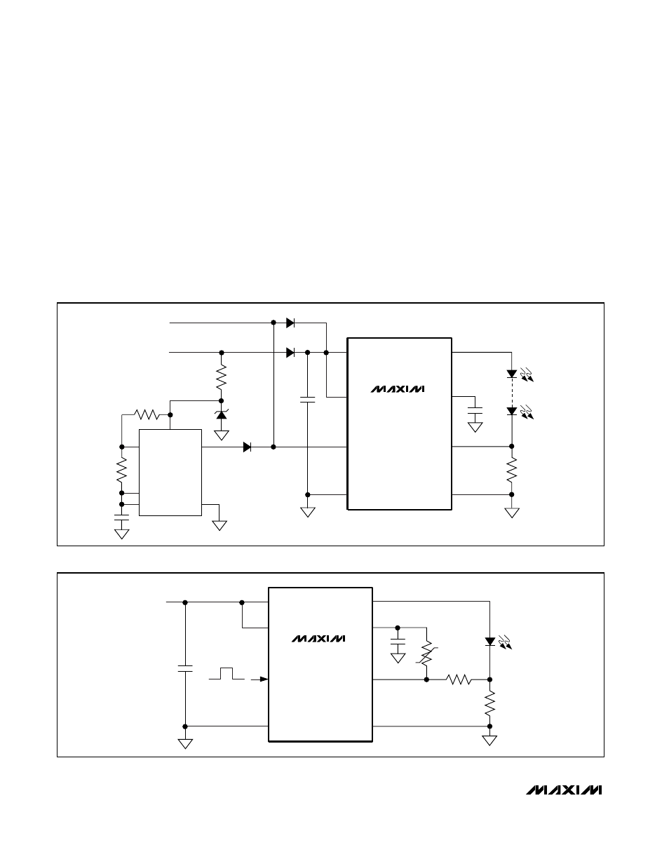
Figure 4 shows PWM dimming operation for the
MAX16803 with an ICM7555 timer. The ICM7555 pro-
vides adjustable duty cycle using two external resistors
and a capacitor. In TAIL operation, the output of the
ICM7555 feeds into DIM and lights up the LEDs. The
LED’s brightness depends on the duty cycle of the
ICM7555. When V
STOP
is present, DIM is pulled up to
V
STOP
. The PWM dimming operation is disabled and
the LEDs light up to full brightness. See the ICM7555
data sheet for formulas to calculate the dimming fre-
quency and the duty cycle.
LED Current Thermal Foldback
With a minimum number of external components, the
MAX16803 provides LED current thermal foldback
using a negative temperature coefficient (NTC) thermis-
tor. Figure 5 shows a thermistor connected to V5 and
the CS+ of the MAX16803. As the temperature increas-
es, the voltage drop across R2 increases causing the
LED current to decrease.
I
LED
= [V
SENSE
- [R2 / (R2 + RT)] x V5] / R1
High-Voltage, 350mA, High-Brightness LED
Driver with PWM Dimming and 5V Regulator
8
_______________________________________________________________________________________
IN
EN
DIM
CS-
CS+
OUT
GND
GND
OUT
TRG
DIS
IN
R2
ICM7555
C1
D2
TAIL
STOP
V5
R
SENSE
TH
MAX16803
C2
+5V REG
D1
D4
D3
R1
LEDs
R3
C3
Figure 4. PWM Dimming Operation with ICM7555 Timer
IN
EN
DIM
CS-
CS+
OUT
GND
R1
LEDs
C1
V
IN
V5
R2
RT
PWM DIMMING
MAX16803
C2
Figure 5. LED Current Thermal Foldback with an NTC Thermistor