Input-voltage considerations, Low-frequency pwm dimming at the output – Rainbow Electronics MAX16803 User Manual
Page 7
MAX16803
High-Voltage, 350mA, High-Brightness LED
Driver with PWM Dimming and 5V Regulator
_______________________________________________________________________________________
7
Input-Voltage Considerations
For proper operation, the minimum input voltage must
always be:
V
IN(MIN)
≥ V
RSENSE(MAX)
+ V
FT(MAX)
+ ∆V
DO(MAX)
where V
FT(MAX)
is the total forward voltage of all series
connected LEDs. The minimum operating voltage of the
device is +6.5V. The device operates below +6.5V; how-
ever, output current may not meet the full regulation
specification (see the Typical Operating Characteristics).
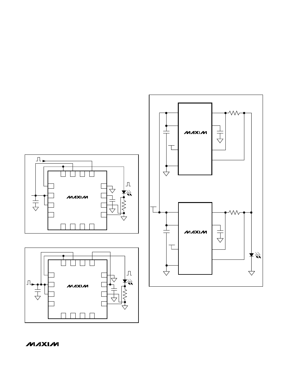
Low-Frequency PWM Dimming at the Output
The MAX16803 provides pulsed or chopped current
dimming input (DIM). The other method is to connect
DIM to V5 and EN to IN and pulse EN. Both methods
generate a regulated-amplitude PWM current (variable
duty cycle) that can provide control over the LED
brightness (see Figures 1 and 2).
Paralleling Multiple MAX16803s to Drive
One High-Power LED
For applications that require more than 350mA of LED
current, two or more MAX16803s can be paralleled
(see Figure 3). V
CS_
should not exceed 4.1V.
3
4
2
1
10
9
11
12
5
6
IN
8
16
15
13
IN
C1
V
IN
N.C.
GND
V5
CS-
C2
D1
R
SENSE
CS+
MAX16803
7
N.C.
N.C.
N.C.
N.C.
OUT
EN
DIM
N.C.
14
OUT
V
DIM
I
LED
Figure 1. Dimming with EN Connected to V
IN
at a Constant
Voltage and DIM Pulsed
3
4
2
1
10
9
11
12
5
6
IN
8
16
15
13
IN
C1
V
IN
N.C.
GND
V5
CS-
C2
D1
R
SENSE
CS+
MAX16803
7
N.C.
N.C.
N.C.
N.C.
OUT
EN
DIM
N.C.
14
OUT
I
LED
Figure 2. Dimming with DIM Connected to V5, EN Connected
to V
IN
MAX16803
IN
OUT
V5
V5
C1
CS+
C2
R1
CS-
GND
EN
DIM
V5
LEDs
MAX16803
IN
OUT
V5
V5
C3
CS+
C4
R2
CS-
GND
EN
DIM
Figure 3. Paralleling MAX16803s