6 pin & package configuration, 1 pin configuration, Atvaultic200 – Rainbow Electronics ATVaultIC200 User Manual
Page 16
16
TPR0460AX–SMS–02/10
ATVaultIC200
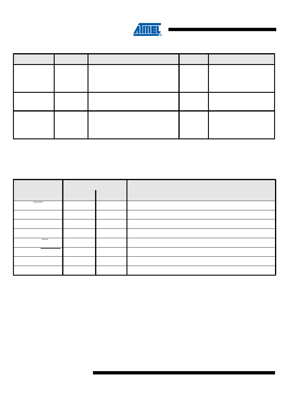
Table 3-6.
External components, Bill of Materials
3.6
Pin & Package Configuration
3.6.1
Pin Configuration
Table 3-7.
Pin List Configuration
Others pins are not connected (do not connect to GND).
When communicating with SPI, all pins not used for SPI must not be connected (do not connect
to GND).
Configuration
Reference
Description
Typ.Value
Comment
I
2
C
R1, R2
Pull-Up Resistors
2.2 k
Ω
Recommended
C1
Power Supply Decoupling Capacitors
4.7 μF
Recommended
C2
Power Supply Decoupling Capacitors
10 nF
Recommended
SPI
C1
Power Supply Decoupling Capacitors
4.7 μF
Recommended
C2
Power Supply Decoupling Capacitors
10 nF
Recommended
ISO7816
R1
Pull-Up Resistor
20 k
Ω
usually on reader side
C1
Power Supply Decoupling Capacitors
4.7 μF
usually on reader side
C2
Power Supply Decoupling Capacitors
10 nF
usually on reader side
Designation
Pin #
Description
SOIC8
DFN8
RST
6
6
CPU reset
VCC
7
7
Power supply
MISO
8
8
SPI Master Input Slave Output
MOSI
1
1
SPI Master Output Slave Input
SCL / SS
3
3
I²C SCL / SPI Slave Select
IO0 / SDA / SPI_SEL
4
4
ISO7816 I/O0 / I²C SDA / SPI/I²C selection PIN
CLK / SCK
5
5
ISO7816 CLK / SPI Master clock
GND
2
2
Ground (reference voltage)