Pin description, Typical operating characteristics (continued) – Rainbow Electronics MAX8804Z User Manual
Page 6
MAX8804Y/MAX8804Z
High-Voltage, Dual-Input, USB/AC
Adapter Chargers in 2mm x 3mm TDFN
6
_______________________________________________________________________________________
Pin Description
PIN
NAME
FUNCTION
1
BAT
Battery Connection. The IC delivers charging current and monitors battery voltage using BAT. Bypass BAT to
GND with a 2.2µF or larger ceramic capacitor. BAT is high impedance when the IC is disabled.
2
USBPWR
USB Power Status Output. USBPWR is internally pulled low if a valid voltage is present at USB, otherwise it is
high impedance. USBPWR circuitry is active regardless of SET and charger on/off status.
3
POK
Power-OK Monitor. POK is an open-drain output that is internally pulled low when a valid charging source is
detected at either DC or USB. POK is high impedance when both input voltages are less than V
UVLO
or V
BAT
.
4
DC
DC Input Supply. Connect DC to a 4.15V to 7V charging source. Bypass DC to GND with a 1µF or larger
ceramic capacitor. DC takes priority over USB when both are valid.
5
USB
USB Input Source. Connect USB to a USB port. Bypass USB to GND with a 1µF or larger ceramic capacitor.
6
CHG
Charging-Status Output. CHG is internally pulled low when the battery is being charged. CHG is high
impedance when the charger is in top-off mode or disabled.
7
SET
Enable/Disable, Charging Current, and Top-Off Threshold Set Input. Drive SET low to enable DC charge
mode and drive high to enable USB charge mode. If both DC and USB inputs are present, SET is used for
the DC charge mode only and USB charge is disabled. SET is also used for programming the charge current
and top-off threshold. See the DC/USB Mode and Charging Current Setting section for details.
8
GND
Ground
—
EP
Exposed Paddle. Connect to the GND plane for optimum thermal dissipation.
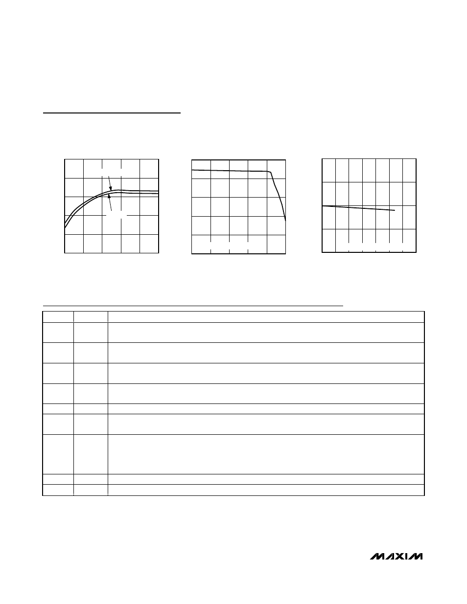
CHARGE CURRENT
vs. AMBIENT TEMPERATURE
AMBIENT TEMPERATURE (
°C)
CHARGE CURRENT (mA)
MAX8804Y/Z toc13
-40
-15
10
35
60
85
200
300
400
500
600
700
DC CHARGE MODE 650mA
BATTERY REGULATION VOLTAGE
vs. LOAD CURRENT
LOAD CURRENT (mA)
BATTERY REGULATION VOLTAGE (V)
MAX8804Y/Z toc14
0
100
200
300
400
500
600
700
4.10
4.15
4.20
4.25
4.30
550mA CHARGE-CURRENT SETTING
Typical Operating Characteristics (continued)
(V
BAT
= 3.6V; DC charge mode: V
DC
= 5V, V
USB
= 0V, V
SET
= 0V or unconnected; USB charge mode: V
USB
= 5V, V
DC
= 0V, V
SET
=
5V; T
A
= +25°C, unless otherwise noted.)
BATTERY REGULATION VOLTAGE
vs. AMBIENT TEMPERATURE
AMBIENT TEMPERATURE (
°C)
BATTERY REGULATION VOLTAGE (V)
MAX8804Y/Z toc12
-40
-15
10
35
60
85
4.180
4.186
4.192
4.198
4.204
4.210
USB MODE
DC MODE