Rainbow Electronics MAX8804Z User Manual
Page 2
MAX8804Y/MAX8804Z
High-Voltage, Dual-Input, USB/AC
Adapter Chargers in 2mm x 3mm TDFN
2
_______________________________________________________________________________________
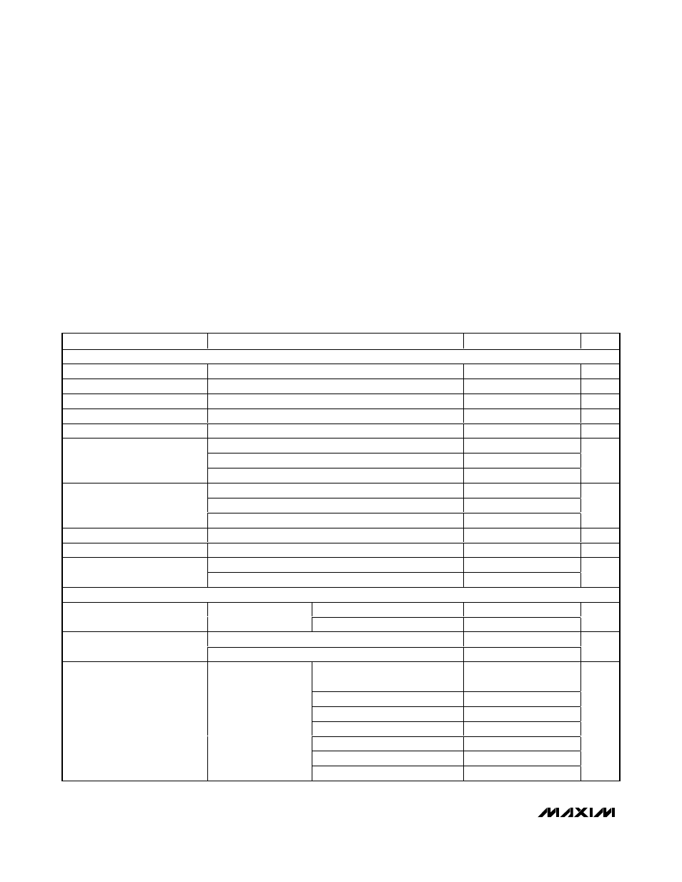
ABSOLUTE MAXIMUM RATINGS
ELECTRICAL CHARACTERISTICS
((V
DC
= 5V, V
SET
= 0V) or (V
USB
= 5V, V
SET
= 5V), V
BAT
= unconnected, T
A
= -40°C to +85°C, unless otherwise noted.) (Note 1)
Stresses beyond those listed under “Absolute Maximum Ratings” may cause permanent damage to the device. These are stress ratings only, and functional
operation of the device at these or any other conditions beyond those indicated in the operational sections of the specifications is not implied. Exposure to
absolute maximum rating conditions for extended periods may affect device reliability.
DC to GND .............................................................-0.3V to +30V
USB to GND ...........................................................-0.3V to +16V
BAT, CHG, SET, POK, USBPWR to GND ..............-0.3V to +5.5V
Continuous Power Dissipation (T
A
= +70°C)
8-Pin TDFN 2mm x 3mm (derate 16.7mW/°C above +70°C)
(multilayer board) .......................................................1333mW
Operating Temperature Range ...........................-40°C to +85°C
Junction Temperature ......................................................+150°C
Storage Temperature Range .............................-65°C to +150°C
Lead Temperature (soldering, 10s) .................................+300°C
PARAMETER
CONDITIONS
MIN
TYP
MAX
UNITS
DC AND USB
DC Input Voltage Range
0
28
V
USB Input Voltage Range
0
14
V
Input Operating Range
(Notes 2, 3)
4.15
7.00
V
Input Undervoltage Threshold
V
IN
rising, 500mV hysteresis (typ) (Note 2)
3.85
4.0
4.15
V
Input Overvoltage Threshold
V
IN
rising, 200mV hysteresis (typ) (Note 2)
7.2
7.5
7.8
V
V
USB
= 0V, I
BAT
= 0mA, charge mode
800
1200
V
SET
= 5V, standby mode
300
550
DC Input Supply Current
V
DC
= V
BAT
= 4.3V, shutdown mode
300
550
µA
V
DC
= 0V, V
SET
= 5V, I
BAT
= 0mA, charge mode
800
1200
V
SET
= 0V, standby mode
300
550
USB Input Supply Current
V
USB
= V
BAT
= 4.3V, shutdown mode
300
550
µA
DC to BAT On-Resistance
V
DC
= 3.7V, V
BAT
= 3.6V
0.55
1.0
Ω
USB to BAT On-Resistance
V
USB
= 3.7V, V
BAT
= 3.6V
0.65
1.2
Ω
V
IN
rising
145
260
385
Input to BAT Comparator
Threshold (Note 2)
V
IN
falling
55
mV
BAT
T
A
= +25°C
4.179
4.200
4.221
BAT Regulation Voltage
I
BAT
= 0mA
T
A
= -40°C to +85°C
4.158
4.200
4.242
V
V
BAT
rising
4.40
4.67
4.90
Battery Removal Detection
Threshold
Hysteresis
0.1
V
Default and 1st to 3rd interface
pulse
475
500
525
4th to 7th interface pulse
523
550
578
8th to 11th interface pulse
570
600
630
12th to 15th interface pulse
428
450
473
16th to 19th interface pulse
380
400
420
20th to 23rd interface pulse
618
650
683
DC Charging Current
V
USB
= 0V,
V
BAT
= 3.6V,
rising edge detection
on SET
24th to 27th interface pulse
665
700
735
mA