Chip information, Pin configuration – Rainbow Electronics MAX8804Z User Manual
Page 13
Layout and Bypassing
Connect the input capacitors as close as possible to
the IC. Provide a large copper GND plane to allow the
exposed paddle to sink heat away from the IC. Connect
the battery to BAT as close as possible to the IC to pro-
vide accurate battery voltage sensing. Make all high-
current traces short and wide to minimize voltage
drops. A sample layout is available in the MAX8804Z
evaluation kit to speed designs.
MAX8804Y/MAX8804Z
High-Voltage, Dual-Input, USB/AC
Adapter Chargers in 2mm x 3mm TDFN
______________________________________________________________________________________
13
DC
CHG
POK
BAT
USB
GND
USBPWR
SET
USB PORT
μP
SYSTEM I/O
2.2
μF
MAX8804Y
MAX8804Z
AC
ADAPTER
1
μF
1
μF
Li+
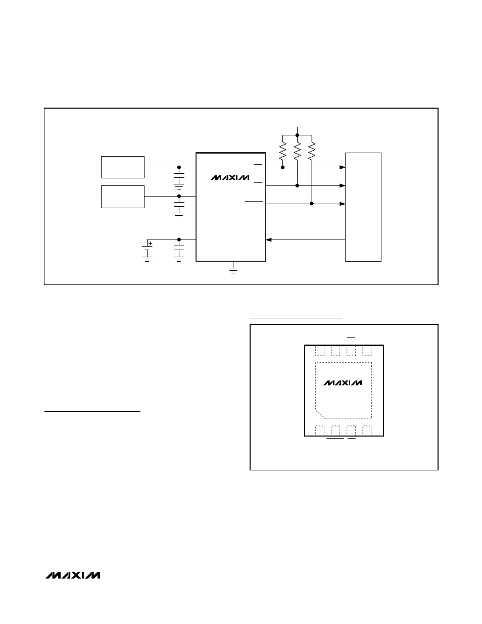
Figure 5. Microprocessor-Interfaced Li+ Charger with the MAX8804Y/MAX8804Z
Chip Information
PROCESS: BiCMOS
1
+
3
4
8
6
5
GND
CHG
USB
MAX8804Y
MAX8804Z
2
7
SET
BAT
POK
DC
USBPWR
TDFN
2mm
× 3mm
TOP VIEW
Pin Configuration
- MAX5151 (16 pages)
- MAXQ3108 (64 pages)
- MAX5661 (39 pages)
- MAX6691 (7 pages)
- MAX5362 (12 pages)
- ADC10158 (26 pages)
- MAX8922L (14 pages)
- MAX8596Z (8 pages)
- MAX7491 (18 pages)
- MAX15040 (15 pages)
- MAX5177 (16 pages)
- ADC08138 (22 pages)
- MAX5961 (42 pages)
- T89C51RD2 (86 pages)
- MAX16055 (9 pages)
- MAX6659 (17 pages)
- ADC0820 (20 pages)
- MAX6678 (19 pages)
- MAX8884Z (15 pages)
- MAX16915 (9 pages)
- MAX8620 (18 pages)
- MAX5144 (12 pages)
- MAX6670 (8 pages)
- MAX8760 (39 pages)
- W78C32C (14 pages)
- MX7533 (8 pages)
- MAX8727 (13 pages)
- MAX9053 (15 pages)
- W78C54 (16 pages)
- MAX8614B (15 pages)
- W90N740 (219 pages)
- MAX6626 (13 pages)
- ADC10738 (30 pages)
- MAX17000 (31 pages)
- MAX5051 (21 pages)
- MAXQ1004 (18 pages)
- MAX6871 (51 pages)
- MX7847 (12 pages)
- MAX6608 (6 pages)
- MAX17083 (15 pages)
- MAX6641 (17 pages)
- MAX5251 (16 pages)
- MAX6338 (8 pages)
- MAX6690 (16 pages)
- MAX8668 (18 pages)