Applications information – Rainbow Electronics MAX16074 User Manual
Page 7
_______________________________________________________________________________________ 7
MAX16072/MAX16073/MAX16074
µP Supervisory Circuits in
4-Bump (1mm x 1mm) Chip-Scale Package
Manual Reset Input (MR)
Many FP-based products require manual-reset capabil-
ity, allowing the operator, a test technician, or external
logic circuit to initiate a reset. A logic-low on MR asserts
reset. Reset remains asserted while MR is low, and for
the reset active timeout period (t
RP
) or delay (t
ON
) after
MR returns high. This input has an internal 50kI pullup
resistor, so it can be left unconnected if it is not used.
MR can be driven with TTL or CMOS logic levels, or
with open-drain/collector outputs. For manual operation,
connect a normally open momentary switch from MR to
GND; external debouncing circuitry is not required. If MR
is driven from long cables or if the device is used in a
noisy environment, connect a 0.1FF capacitor from MR to
ground to provide additional noise immunity.
Applications Information
Interfacing to
µ
P with
Bidirectional Reset Pins
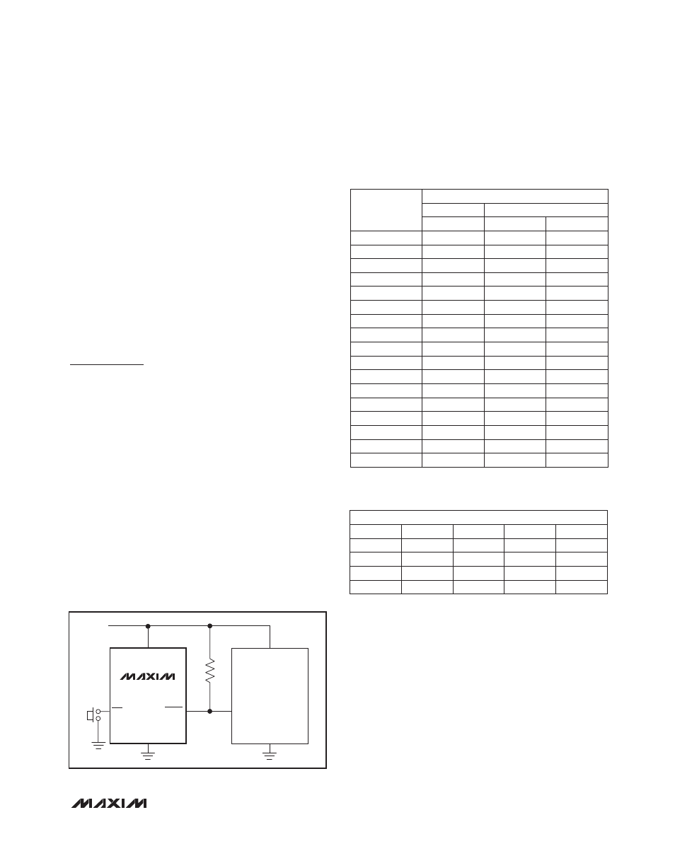
Since RESET on the MAX16074 is open-drain, this
device interfaces easily with FPs that have bidirectional
reset pins. Connecting the FP supervisor’s RESET output
directly to the FP’s RESET pin with a single pullup resis-
tor allows either device to assert reset (Figure 2).
Negative-Going V
CC
Transients
The MAX16072/MAX16073/MAX16074 family of devic-
es is relatively immune to short-duration, negative-
going V
CC
transients (glitches). The Typical Operating
Characteristics show the Maximum Transient Duration
vs. Reset Threshold Overdrive graph, for which reset
pulses are not generated. The graph shows the maxi-
mum pulse width that a negative-going V
CC
transient
may typically have when issuing a reset signal. As the
amplitude of the transient increases, the maximum allow-
able pulse width decreases.
Figure 2. Interfacing to
µ
P with Bidirectional Reset Pins
Table 1. Factory Trimmed Reset
Thresholds
Table 2. Reset Timeout Periods
RESET
INPUT
V
CC
µP
V
CC
RESET
GND
GND
V
CC
MR
MAX16074
MOTOROLA
68HCXX
THRESHOLD
SUFFIX
RESET TRIP THRESHOLD (V)
T
A
= +25NC
T
A
= -40NC to +85NC
TYP
MIN
MAX
15
1.58
1.54
1.61
16
1.63
1.60
1.66
17
1.67
1.62
1.71
18
1.80
1.76
1.85
19
1.90
1.85
1.95
20
2.00
1.95
2.05
21
2.10
2.05
2.15
22
2.20
2.145
2.25
23
2.32
2.262
2.375
24
2.40
2.34
2.46
25
2.50
2.437
2.562
26
2.63
2.564
2.69
27
2.70
2.633
2.768
28
2.80
2.63
2.87
29
2.93
2.857
3.0
30
3.00
2.925
3.075
31
3.08
3.003
3.15
RESET TIMEOUT PERIODS
SUFFIX
MIN
TYP
MAX
UNITS
0
20
80
120
F
s
1
8
13
17
ms
2
34
52
69
ms
3
140
210
280
ms