Functional diagrams detailed description – Rainbow Electronics MAX16074 User Manual
Page 6
6 ______________________________________________________________________________________
MAX16072/MAX16073/MAX16074
µP Supervisory Circuits in
4-Bump (1mm x 1mm) Chip-Scale Package
Functional Diagrams
Detailed Description
The MAX16072/MAX16073/MAX16074 ultra-small, ultra-
low-power, µP supervisory circuits feature a precision
band-gap reference, comparator, and internally trimmed
resistors that set specified trip threshold voltages.
Designed to monitor the system supply voltage and an
output during power-up, power-down, and brownout
conditions, these devices provide excellent circuit reli-
ability and low cost by eliminating external components
and adjustments when monitoring nominal system volt-
age from 1.8V to 3.6V.
The MAX16072 has a push-pull active-low reset output,
the MAX16073 has a push-pull active-high reset output,
and the MAX16074 has an open-drain active-low reset
output. The devices are designed to ignore fast tran-
sients on V
CC
. The devices also include a manual reset
input (MR). When MR is low, reset is asserted. When MR
is high and V
CC
is above the detector threshold (V
TH
),
reset is not asserted.
Supply and Monitored Input (V
CC
)
The MAX16072/MAX16073/MAX16074 operate with a
V
CC
supply voltage from 1.2V to 2.75V. V
CC
has a rising
threshold of V
TH
+ V
HYST
and a falling threshold of V
TH
.
When V
CC
rises above V
TH
+ V
HYST
and MR is high,
RESET goes high (RESET goes low) after the reset time-
out period (t
RP
). See Figure 1.
When V
CC
falls below V
TH
, RESET goes low (RESET
goes high) after a fixed delay (t
RD
).
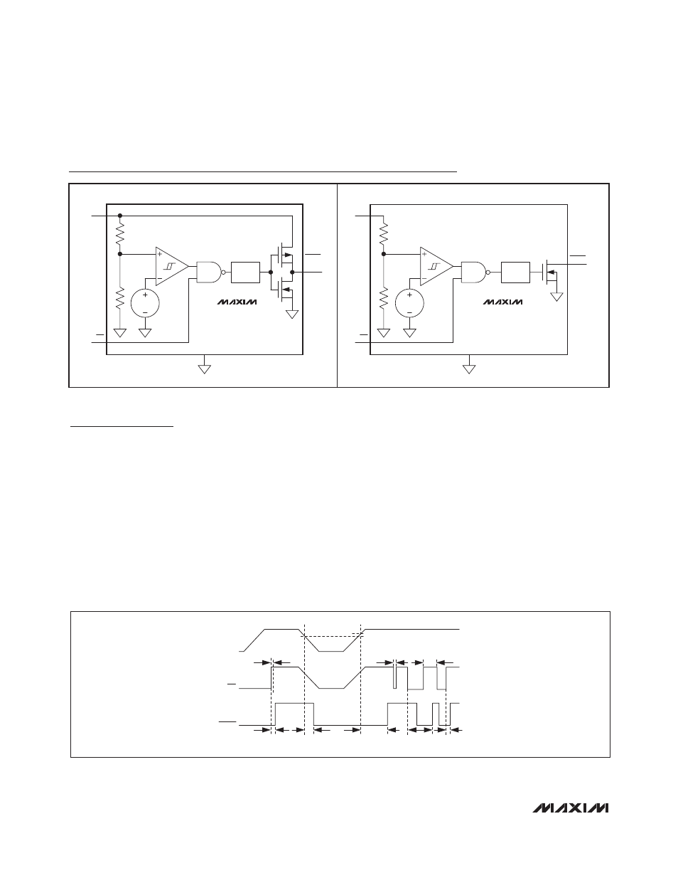
Figure 1. MAX16072/MAX16073/MAX16074 Timing Diagram
( ) MAX16073 ONLY
RESET
TIMEOUT
RESET
(RESET)
V
CC
GND
MR
MAX16074
MAX16072
MAX16073
RESET
TIMEOUT
RESET
V
CC
GND
MR
MR
t
MPW
t
ON
t
DL
t
RP
t
OFF
t
ON
t < t
EGR
t < t
MPW
RESET
V
CC
V
TH
V
TH
+ V
HYST