Bump description bump configuration – Rainbow Electronics MAX16074 User Manual
Page 5
_______________________________________________________________________________________ 5
MAX16072/MAX16073/MAX16074
µP Supervisory Circuits in
4-Bump (1mm x 1mm) Chip-Scale Package
Bump Description
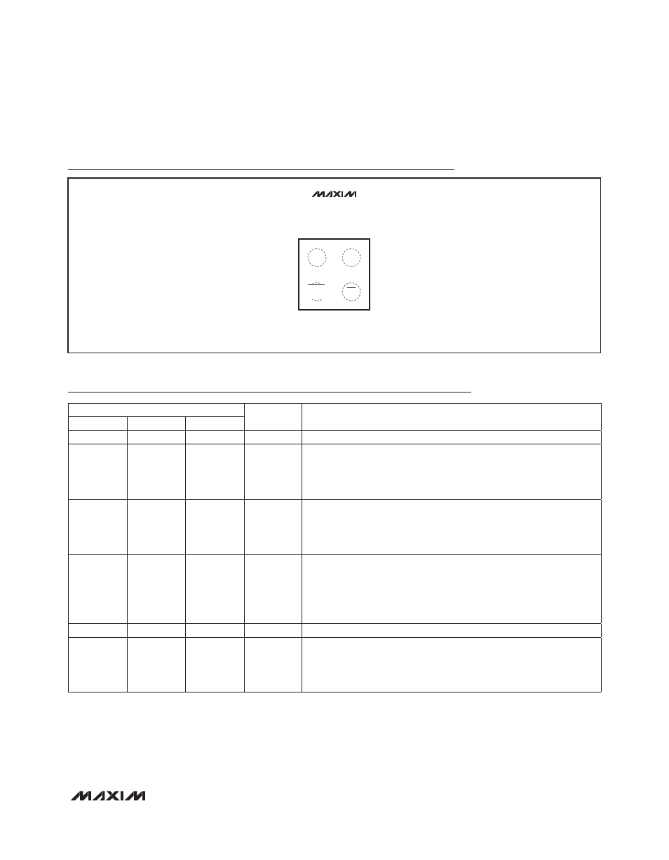
Bump Configuration
UCSP
( ) FOR THE MAX16073 ONLY
MAX16072
MAX16073
MAX16074
TOP VIEW
(BUMP SIDE DOWN)
1
2
B
A
+
GND
V
CC
MR
RESET/
(RESET)
BUMP
NAME
FUNCTION
MAX16072
MAX16073
MAX16074
A1
A1
A1
GND
Ground
B1
—
—
RESET
Active-Low Push-Pull Reset Output. RESET changes from high to
low when V
CC
drops below the detector threshold (V
TH
) or MR is
pulled low. RESET remains low for the reset timeout period after V
CC
exceeds V
TH
and MR is high. When MR is low, RESET is low.
—
B1
—
RESET
Active-High Push-Pull Reset Output. RESET changes from low to
high when V
CC
drops below the detector threshold (V
TH
) or MR is
pulled low. RESET remains high for the reset timeout period after V
CC
exceeds V
TH
and MR is high. When MR is low, RESET is high.
—
—
B1
RESET
Active-Low Open-Drain Reset Output. RESET changes from high-
impedance to active-low when V
CC
drops below the detector thresh-
old (V
TH
) or MR is pulled low. RESET remains low for the reset timeout
period after V
CC
exceeds the reset threshold and MR is high. When
MR is low, RESET is low.
A2
A2
A2
V
CC
Supply Voltage and Input for the Reset Threshold Monitor
B2
B2
B2
MR
Active-Low Manual-Reset Input. Drive low to force a reset. Reset
remains active as long as MR is low and for the reset timeout period (if
applicable) after MR is driven high. MR has an internal pullup resistor
connected to V
CC,
and may be left unconnected if not used.