Rainbow Electronics MAX6616 User Manual
Page 8
MAX6615/MAX6616
ture. The thermistor data in the temperature register(s)
gives the voltage across R
EXT
as a fraction of the refer-
ence voltage. The LSB of the high byte has a nominal
weight of 7.68mV.
O
OT
T
Output
The OT output asserts when a thermal fault occurs, and
can therefore be used as a warning flag to initiate sys-
tem shutdown, or to throttle clock frequency. When
temperature exceeds the OT temperature threshold
and OT is not masked, the OT status register indicates
a fault and OT output becomes asserted. If OT for the
respective channel is masked off, the OT status register
continues to be set, but the OT output does not
become asserted.
The fault flag and the output can be cleared by reading
the OT status register. The OT output can also be
cleared by masking the affected channel. If the OT sta-
tus bit is cleared, OT reasserts on the next conversion if
the temperature still exceeds the OT temperature
threshold.
PWM Output
The PWM_ signals are normally used in one of three
ways to control the fan’s speed:
1) PWM_ drives the gate of a MOSFET or the base of a
bipolar transistor in series with the fan’s power sup-
ply. The Typical Application Circuit shows the PWM_
driving an n-channel MOSFET. In this case, the PWM
invert bit (D4 in register 02h) is set to 1.
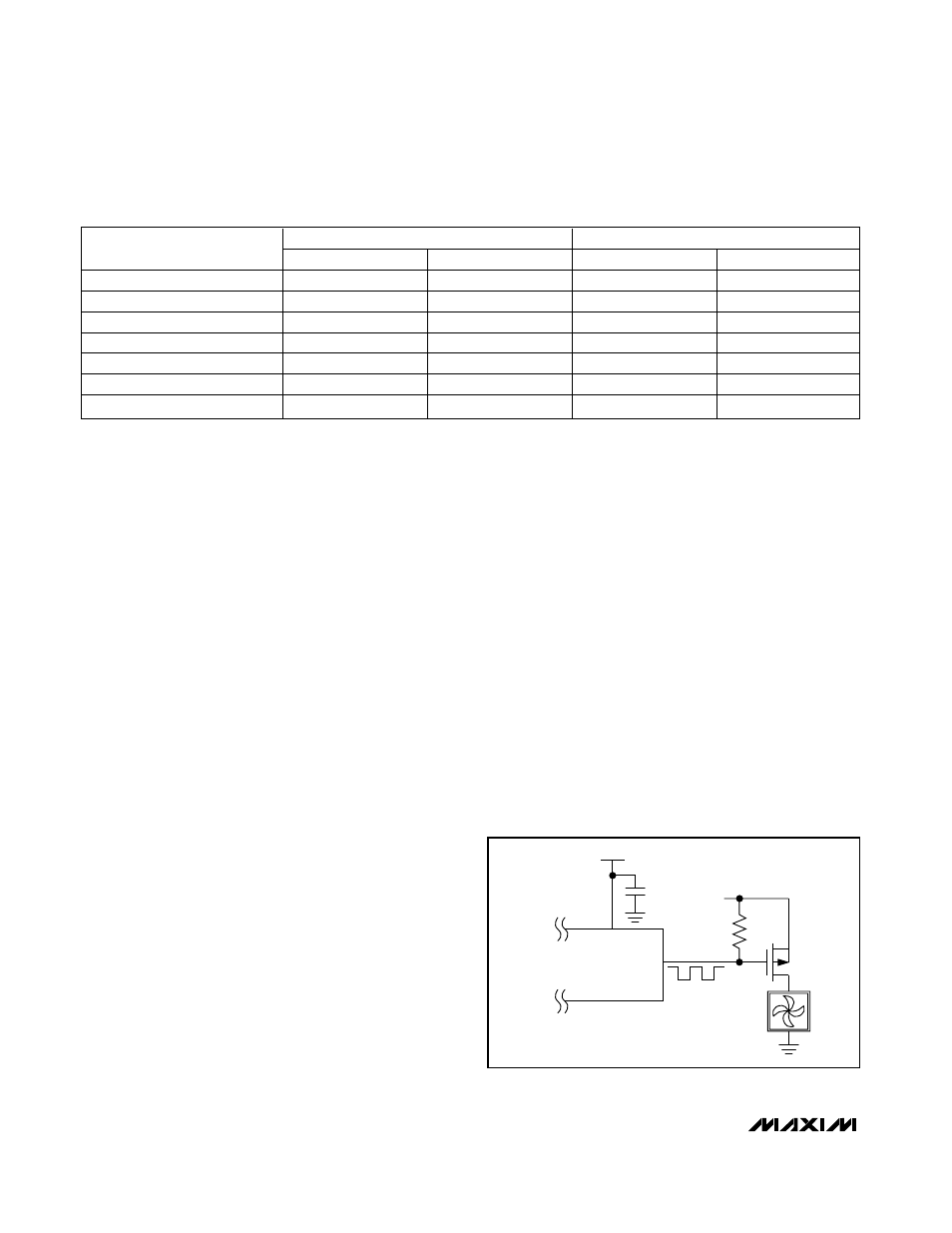
Figure 4
shows PWM_ driving a p-channel MOSFET and the
PWM invert bit must be set to zero.
2) PWM_ is converted (using an external circuit) into a
DC voltage that is proportional to duty cycle. This
duty-cycle-controlled voltage becomes the power
supply for the fan. This approach is less efficient
than (1), but can result in quieter fan operation.
Figure 5 shows an example of a circuit that converts
the PWM signal to a DC voltage. Because this circuit
produces a full-scale output voltage when PWM =
0V, bit D4 in register 02h should be set to zero.
3) PWM_ directly drives the logic-level PWM speed-
control input on a fan that has this type of input. This
approach requires fewer external components and
combines the efficiency of (1) with the low noise of
(2). An example of PWM_ driving a fan with a speed-
control input is shown in Figure 6. Bit D4 in register
02h should be set to 1 when this configuration is
used.
Whenever the fan has to start turning from a motionless
state, PWM_ is forced high for 2s. After this spin-up
period, the PWM_ duty cycle settles to the predeter-
mined value. Whenever spin-up is disabled (bit 2 in the
configuration byte = 1) and the fan is off, the duty cycle
changes immediately from zero to the nominal value,
ignoring the duty-cycle rate-of-change setting.
The frequency-select register controls the frequency of
the PWM signal. When the PWM signal modulates the
power supply of the fan, a low PWM frequency (usually
33Hz) should be used to ensure the circuitry of the
Dual-Channel Temperature Monitors and
Fan-Speed Controllers with Thermistor Inputs
8
____________________________________________________
Table 1. Temperature Data Format (High Byte and Low Byte)
HIGH BYTE
LOW BYTE
TEMPERATURE (°C)
BINARY VALUE
HEX VALUE
BINARY VALUE
HEX VALUE
140.0
1000 1100
8Ch
0000 0000
00h
127.0
0111 1111
7Fh
0000 0000
00h
25.375
0001 1001
19h
0110 0000
60h
25.0
0001 1001
19h
0000 0000
00h
0.5
0000 0000
00h
1000 0000
80h
0.0
0000 0000
00h
0000 0000
00h
<0
0000 0000
00h
0000 0000
00h
V
CC
PWM
10k
Ω
5V
P
Figure 4. Driving a p-Channel MOSFET for Top-Side PWM Fan
Drive