Detailed description – Rainbow Electronics MAX6616 User Manual
Page 6
MAX6615/MAX6616
Detailed Description
The MAX6615/MAX6616 accurately monitor two tem-
perature channels, either the internal die temperature
and the temperature of an external thermistor, or the
temperatures of two external thermistors. They report
temperature values in digital form using a 2-wire
SMBus/I
2
C*-compatible serial interface. The MAX6615/
MAX6616 operate from a supply voltage range of 3.0V
to 5.5V and consume 500µA (typ) of supply current.
The temperature data controls the duty cycles of two
PWM output signals that are used to adjust the speed
of a cooling fan. They also feature an overtemperature
alarm output to generate interrupts, throttle signals, or
shutdown signals.
The MAX6616 also includes six GPIO input/outputs to
provide additional flexibility. The GPIO0 power-up state
is set by connecting the GPIO PRESET input to ground
or V
CC
.
SMBus Digital Interface
From a software perspective, the MAX6615/MAX6616
appear as a set of byte-wide registers. Their devices use
a standard SMBus 2-wire/I
2
C-compatible serial interface
to access the internal registers. The MAX6615/MAX6616
have nine different slave addresses available; therefore, a
maximum of nine MAX6615/MAX6616 devices can share
the same bus.
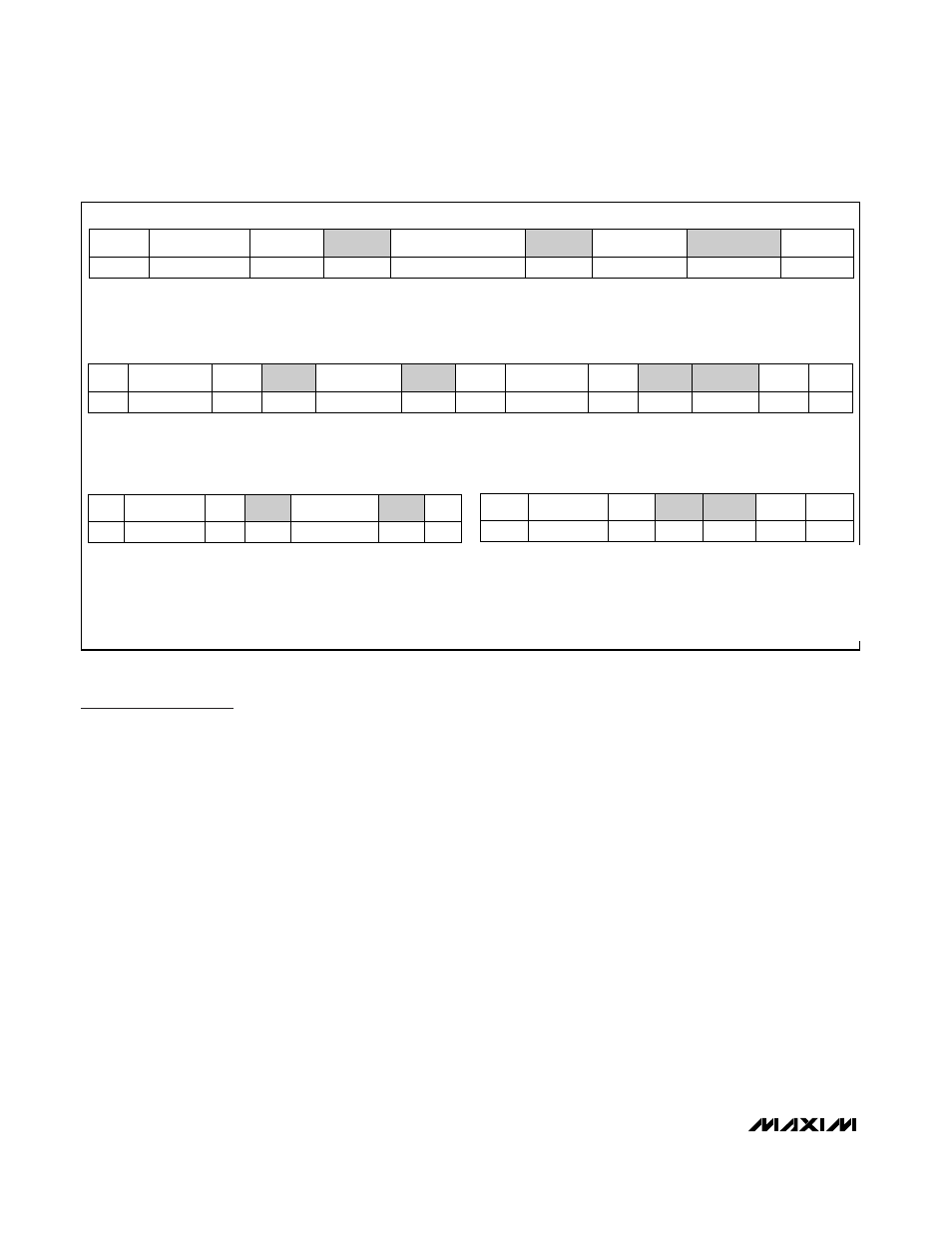
The MAX6615/MAX6616 employ four standard SMBus
protocols: write byte, read byte, send byte, and receive
byte (Figures 1, 2, and 3). The shorter receive byte proto-
col allows quicker transfers, provided that the correct
data register was previously selected by a read byte
instruction. Use caution with the shorter protocols in mul-
timaster systems, since a second master could overwrite
the command byte without informing the first master.
Temperature data can be read from registers 00h and
01h. The temperature data format for these registers is
8 bits, with the LSB representing 1°C (
Table 1) and the
MSB representing 128°C. The MSB is transmitted first.
All values below 0°C clip to 00h.
Table 3 details the register address and function, whether
they can be read or written to, and the power-on reset
Dual-Channel Temperature Monitors and
Fan-Speed Controllers with Thermistor Inputs
6
_______________________________________________________________________________________
WRITE BYTE FORMAT
READ BYTE FORMAT
SEND BYTE FORMAT
RECEIVE BYTE FORMAT
SLAVE ADDRESS: EQUIVA-
LENT TO CHIP-SELECT LINE
OF A 3-WIRE INTERFACE
COMMAND BYTE: SELECTS
WHICH REGISTER YOU ARE
WRITING TO
DATA BYTE: DATA GOES INTO THE REG-
ISTER SET BY THE COMMAND BYTE (TO
SET THRESHOLDS, CONFIGURATION
MASKS, AND SAMPLING RATE)
SLAVE ADDRESS:
EQUIVALENT TO CHIP-
SELECT LINE
COMMAND BYTE:
SELECTS WHICH
REGISTER YOU ARE
READING FROM
SLAVE ADDRESS: REPEAT-
ED DUE TO CHANGE IN
DATA- FLOW DIRECTION
DATA BYTE: READS
FROM THE REGISTER
SET BY THE COMMAND
BYTE
COMMAND BYTE: SENDS COM-
MAND WITH NO DATA, USUALLY
USED FOR ONE-SHOT COMMAND
DATA BYTE: READS DATA FROM
THE REGISTER COMMANDED BY
THE LAST READ BYTE OR WRITE
BYTE TRANSMISSION; ALSO
USED FOR SMBUS ALERT
RESPONSE RETURN ADDRESS
S = START CONDITION
SHADED = SLAVE TRANSMISSION
P = STOP CONDITION
/// = NOT ACKNOWLEDGED
Figure 1. SMBus Protocols
S
ADDRESS
RD
ACK
DATA
///
P
—
7 BITS
—
—
8 BITS
—
—
WR
S
ACK
COMMAND
ACK
P
—
—
—
8 BITS
—
—
ADDRESS
7 BITS
P
1
ACK
—
DATA
8 BITS
ACK
—
COMMAND
8 BITS
ACK
—
WR
—
ADDRESS
7 BITS
S
—
S
ADDRESS
WR
ACK
COMMAND
ACK
S
ADDRESS
7 BITS
—
—
8 BITS
—
—
7 BITS
—
RD
—
ACK
—
DATA
8 BITS
///
—
P
—
*Purchase of I
2
C components from Maxim Integrated Products,
Inc., or one of its sublicensed Associated Companies, conveys
a license under the Philips I
2
C Patent Rights to use these com-
ponents in an I
2
C system, provided that the system conforms
to the I
2
C Standard Specification as defined by Philips.