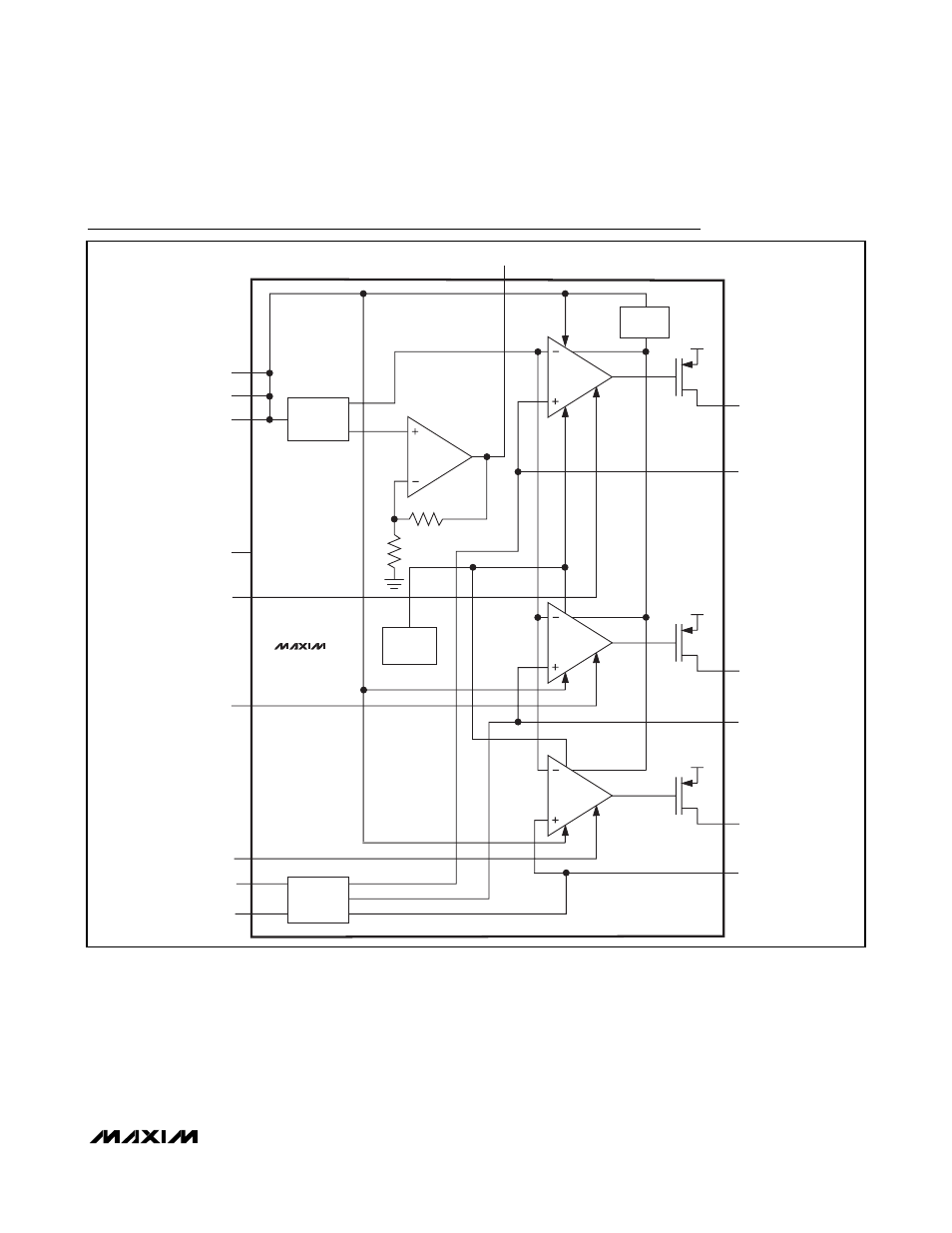
Block diagram – Rainbow Electronics MAX16823 User Manual
Page 7
MAX16823
High-Voltage, 3-Channel Linear High-Brightness
LED Driver with Open LED Detection
_______________________________________________________________________________________
7
Pulse-Dimming Inputs (DIM_)
The MAX16823 features pulsed or chopped-current
dimming inputs (DIM_) to chop the LED current and to
adjust the brightness. DIM_ also serves as an active-
high enable input. A logic-low at DIM_ turns off OUT_
and a logic-high turns on OUT_. If the signal at DIM
stays low more than the programmed LEDGOOD delay
time, LEDGOOD goes low (Figure 1).
Two Brightness Levels for
TAIL/STOP Lights
Figure 2 shows the PWM dimming operation for the
MAX16823 with an ICM7555 timer. The ICM7555 pro-
vides an adjustable duty cycle using two external resis-
tors and a capacitor. In TAIL operation, the output of
the ICM7555 feeds into DIM and lights up the LEDs.
The LED’s brightness depends on the duty cycle of the
I_REG
MAX16823
I_REG
I_REG
IN
IN
IN
OUT1
CS1
OUT2
OUT3
UVLO
THERMAL
SHUTDOWN
LGC
LEDGGOOD
DIM3
DIM2
DIM1
GND
IN
IN
IN
BANDGAP
LEDGOOD
DETECTOR
CS2
CS3
REG
Block Diagram