Detailed description, Pin description – Rainbow Electronics MAX4995 User Manual
Page 7
MAX4995A/AF/AL/MAX4995B/MAX4995C
50mA to 600mA Programmable
Current-Limit Switches
_______________________________________________________________________________________
7
Detailed Description
The MAX4995A/MAX4995AF/MAX4995AL/MAX4995B/
MAX4995C programmable current-limit switches oper-
ate from +1.7V to +5.5V and provide internal current
limiting adjustable from 50mA to 600mA. These devices
feature a fixed blanking time and a
FLAG output that
notifies the processor when a fault condition is present.
Programmable Current Limit
A resistor from SETI to GND programs the current limit
for the switch (see the
Setting the Current Limit
sec-
tion). If the output current exceeds the current limit for a
time equal to or longer than t
BLANK
, the output flag
asserts and the MAX4995A/MAX4995AF/MAX4995AL
enter the autoretry mode. The MAX4995B latches off
the switch, and the MAX4995C enters the continuous
current-limit mode.
Autoretry (MAX4995A/MAX4995AF/
MAX4995AL)
When the forward current reaches the current-limit
threshold, the t
BLANK
timer begins counting (Figure 2).
FLAG asserts if the overcurrent-limit condition is pre-
sent for t
BLANK
. The timer resets if the overcurrent con-
dition disappears before the blanking time (t
BLANK
) has
elapsed. A retry time delay (t
RETRY
) starts immediately
after the blanking time has elapsed and during that
time, the switch latches off. At the end of t
RETRY
, the
switch turns on again. If the fault still exists, the cycle
repeats. If the fault has been removed, the switch stays
on. During this cycle,
FLAG stays low. In autoretry if
the thermal power rating of the package is exceeded,
the MAX4995A/MAX4995AF/MAX4995AL go into ther-
mal shutdown.
The autoretry feature saves system power in case of an
overcurrent or short-circuit condition. During t
BLANK
time when the switch is on, the supply current is held at
the current limit. During time t
RETRY
when the switch is
off, the current through the switch is zero. Thus, the
average output current is much less than the pro-
grammed current limit. Calculate the average output
current using the following equation:
I
LOAD
= I
LIM
[t
BLANK
/(t
BLANK
+ t
RETRY
)]
With a typical t
BLANK
= 16.3ms and typical t
RETRY
=
524ms, the duty cycle is 3%, resulting in a 97% power
savings over the switch being on the entire time.
Latchoff (MAX4995B)
When the forward current reaches the current-limit
threshold, the t
BLANK
timer begins counting (Figure 3).
FLAG asserts if an overcurrent-limit condition is present
for greater than t
BLANK
time. The timer resets if the over-
current condition disappears before t
BLANK
has
elapsed. The switch turns off if the overcurrent condition
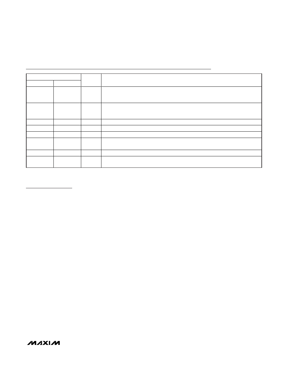
Pin Description
PIN (UTQFN)
MAX4995AL
MAX4995_
NAME
FUNCTION
1, 10
1, 10
IN
Power Input. Bypass IN with a 1µF ceramic capacitor to ground. Use higher capacitance
to prevent large load transients from pulling down the supply voltage if necessary.
Connect both power inputs (IN) together.
2
2
FLAG
Open-Drain, Overload Indicator Output. FLAG goes low when the overload fault duration
exceeds the blanking time, reverse current is detected, thermal shutdown mode is
active, or SETI is connected to ground.
3
—
ON
Active-Low, Switch-On Input. Drive ON low to turn on the switch.
—
3
ON
Active-High, Switch-On Input. Drive ON high to turn on the switch.
4
4
GND
Ground
5
5
SETI
Overload Current Limit Adjust. Connect a resistor from SETI to ground to program the
overcurrent limit. Do not connect any capacitance larger than 20pF to SETI.
6, 9
6, 9
N.C.
No Connect. Not internally connected.
7, 8
7, 8
OUT
Switch Output. Bypass OUT with a 1µF capacitor to ground. Connect both outputs (OUT)
together.