Electrical characteristics (continued) – Rainbow Electronics MAX4995 User Manual
Page 3
MAX4995A/AF/AL/MAX4995B/MAX4995C
50mA to 600mA Programmable
Current-Limit Switches
_______________________________________________________________________________________
3
Note 3: I
LIM
is forward current limit.
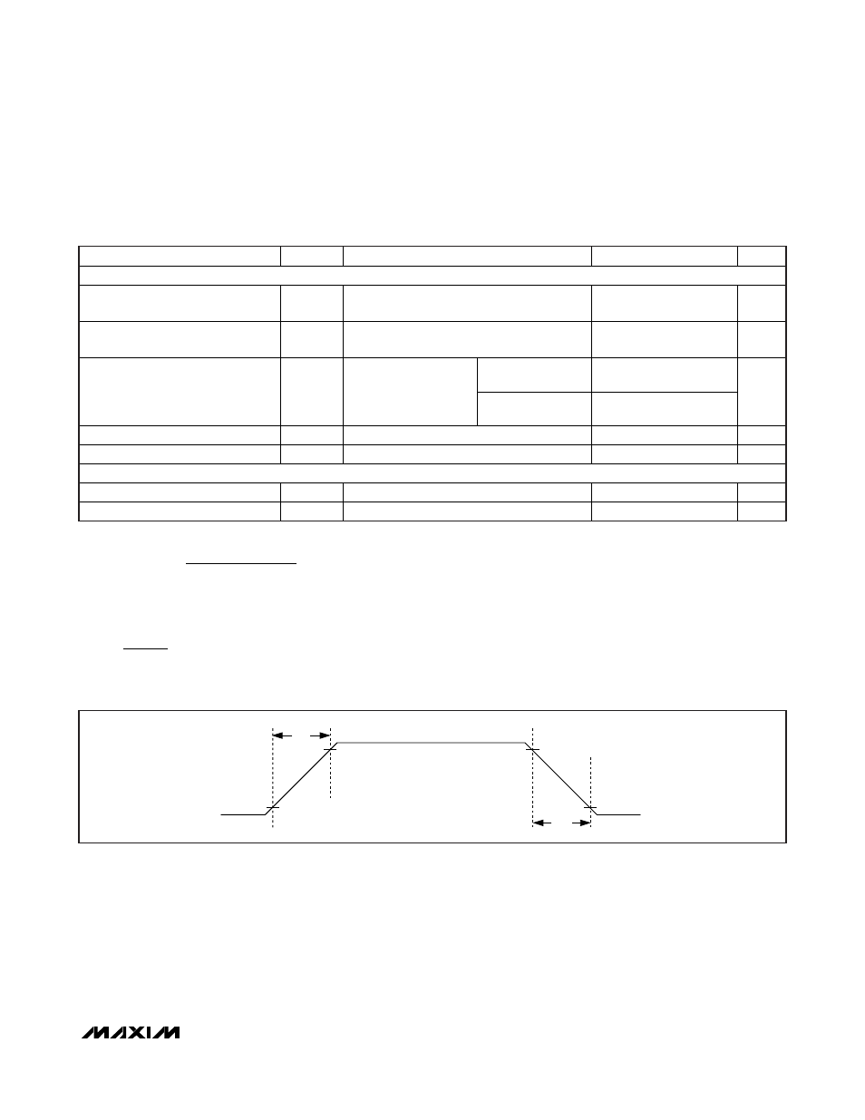
Note 4: Turn-on time and turn-off time are defined as the difference in the time between when the output crosses 10% and 90%
of the final output voltage.
Note 5: Blanking time and retry time are generated by the same oscillator. Therefore, the ratio of
is a constant value of 32. See Figures 2 and 3.
t
t
RETRY
BLANK
I
(mA)
2
R
(k
2.48 k
LIM
SETI
=
+
9042( )
)
(
)
V
Ω
Ω
ELECTRICAL CHARACTERISTICS (continued)
(V
IN
= +1.7V to +5.5V, R
SETI
= 94.3kΩ, C
IN
= 1µF, and T
A
= T
J
= -40°C to +125°C, unless otherwise noted. Typical values are at V
IN
= +3.3V,
T
A
= +25°C.)
PARAMETER
SYMBOL
CONDITIONS
MIN
TYP
MAX
UNITS
DYNAMIC
Turn-On Time
t
SS
V
IN
= 3.3V, C
OUT
= 1µF, R
L
= 20
Ω, Figure 1,
(Note 4)
120
µs
Turn-Off Time
t
OFF
S w i tch fr om on to off, V
I N
= 3.3V , C
OU T
= 1µF,
R
L
= 20
Ω, Figure 1 (Note 4)
120
µs
MAX4995A/AL/B/C
5
Current-Limit Reaction Time
t
LIM
V
IN
= 3.3V, R
SETI
=
578k
Ω, output high
and then short-circuit
applied
MAX4995AF
1.5
µs
Blanking Time
t
BLANK
(Note 5)
10
16.3
22.6
ms
Retry Time
t
RETRY
M AX 4995A/M AX 4995AF/M AX 4995AL ( N ote 5)
320
723.2
ms
THERMAL PROTECTION
Thermal Shutdown
+150
°C
Thermal-Shutdown Hysteresis
15
°C
t
SS
10%
90%
10%
90%
t
OFF
V
OUT
Figure 1. Timing Diagram for Measuring Turn-On Time (t
SS
) and Turn-Off Time (t
OFF
).