C-interface, digital potentiometers, Applications information, Table 2. command byte summary – Rainbow Electronics MAX5419 User Manual
Page 11: Power-up, Standby, Positive lcd bias control, Programmable filter
MAX5417/MAX5418/MAX5419
256-Tap, Nonvolatile, I
2
C-Interface,
Digital Potentiometers
______________________________________________________________________________________
11
ADDRESS BYTE
CONTROL BYTE
DATA BYTE
1
2
3
4
5
6
7
8
9
10
11
12
13
14
15
16
17
18
19
20
21
22
23
24
25
26
27
STOP
SCL
CYCLE
NUMBER
START
A6
A5
A4
A3
A2
A1
A0
ACK
TX
NV
V
R3
R2
R1
R0
ACK
D7
D6
D5
D4
D3
D2
D1
D0
ACK
VREG
0
1
0
1
A2
A1
A0
0
0
0
0
1
0
0
0
1
D7
D6
D5
D4
D3
D2
D1
D0
NVREG
0
1
0
1
A2
A1
A0
0
0
0
1
0
0
0
0
1
D7
D6
D5
D4
D3
D2
D1
D0
NVxVREG
0
1
0
1
A2
A1
A0
0
0
1
1
0
0
0
0
1
D7
D6
D5
D4
D3
D2
D1
D0
VxNVREG
0
1
0
1
A2
A1
A0
0
0
1
0
1
0
0
0
1
D7
D6
D5
D4
D3
D2
D1
D0
Table 2. Command Byte Summary
Nonvolatile Memory
The internal EEPROM consists of an 8-bit nonvolatile
register that retains the value written to it before the
device is powered down. The nonvolatile register is
programmed with the zero-scale value at the factory.
Power-Up
Upon power-up, the MAX5417/MAX5418/MAX5419
load the data stored in the nonvolatile memory register
into the volatile memory register, updating the wiper
position with the data stored in the nonvolatile memory
register. This initialization period takes 10µs.
Standby
The MAX5417/MAX5418/MAX5419 feature a low-power
standby. When the device is not being programmed, it
goes into standby mode and power consumption is
typically 500nA.
Applications Information
The MAX5417/MAX5418/MAX5419 are intended for cir-
cuits requiring digitally controlled adjustable resis-
tance, such as LCD contrast control (where voltage
biasing adjusts the display contrast), or for programma-
ble filters with adjustable gain and/or cutoff frequency.
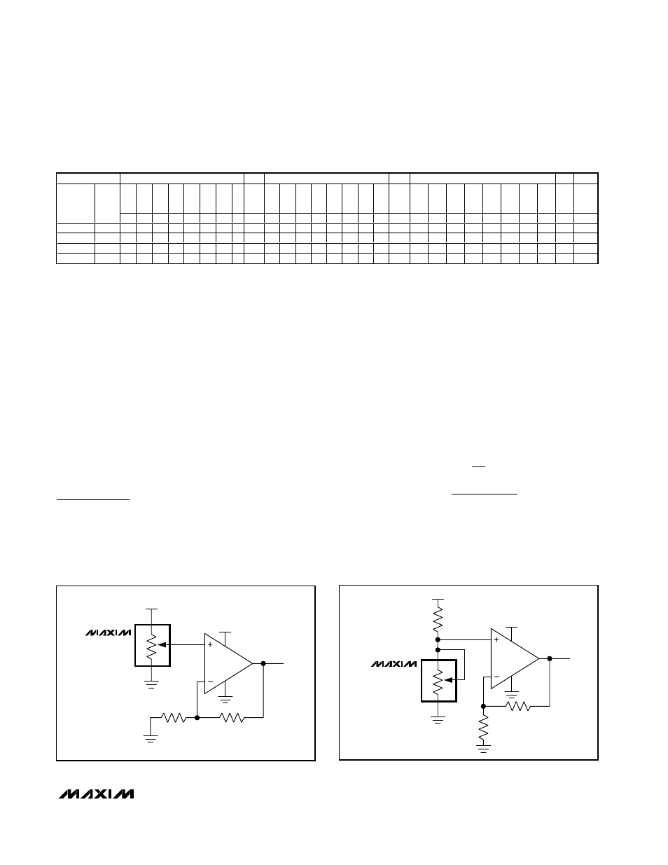
Positive LCD Bias Control
Figures 9 and 10 show an application where the volt-
age-divider or variable resistor is used to make an
adjustable, positive LCD bias voltage. The op amp pro-
vides buffering and gain to the resistor-divider network
made by the potentiometer (Figure 9) or to a fixed
resistor and a variable resistor (see Figure 10).
Programmable Filter
Figure 11 shows the configuration for a 1st-order pro-
grammable filter. The gain of the filter is adjusted by
R2, and the cutoff frequency is adjusted by R3. Use the
following equations to calculate the gain (G) and the
3dB cutoff frequency (f
C
):
G
R
R
f
R
C
C
=
+
=
Ч
Ч
1
1
2
1
2
3
π
V
OUT
30V
5V
W
H
L
MAX5417
MAX5418
MAX5419
V
OUT
30V
5V
W
H
L
MAX5417
MAX5418
MAX5419
Figure 9. Positive LCD Bias Control Using a Voltage-Divider
Figure 10. Positive LCD Bias Control Using a Variable Resistor