Application hints – Rainbow Electronics ADC12138 User Manual
Page 29
Application Hints
(Continued)
With
the
single-ended
multiplexer
configuration
CH0
through CH7 can be assigned to the MUXOUT1 pin The
COM pin is always assigned to the MUXOUT2 pin A DIN1
is assigned as the positve input A DIN2 is assigned as the
negative input (See
Figure 8
)
Differential
Configuration
TL H 12079 – 36
A DIN1 and A DIN2 can be as-
signed as the
a
or
b
input
FIGURE 8
Single-Ended
Configuration
TL H 12079 – 37
A DIN1 is
a
input
A DIN2 is
b
input
The Multiplexer assignment tables for the ADC12130 2 8
(Tables II and III) summarize the aforementioned functions
for the different versions of A Ds
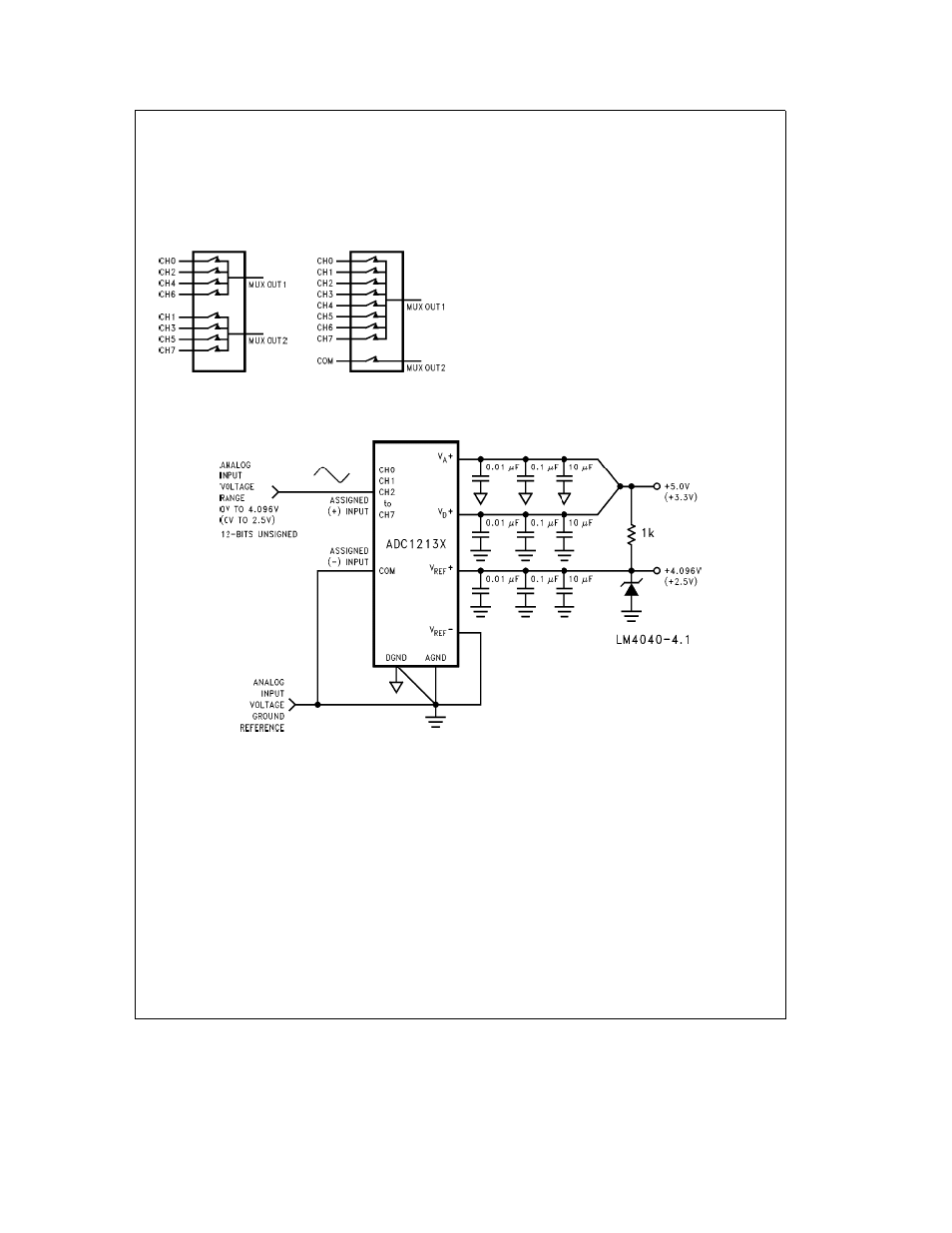
2 1 Biasing for Various Multiplexer Configurations
Figure 9
is an example of biasing the device for single-end-
ed operation The sign bit is always low The digital output
range is 0 0000 0000 0000 to 0 1111 1111 1111 One LSB
is equal to 1 mV (4 1V 4096 LSBs)
TL H 12079 – 38
FIGURE 9 Single-Ended Biasing
29
- MAX5151 (16 pages)
- MAXQ3108 (64 pages)
- MAX5661 (39 pages)
- MAX6691 (7 pages)
- MAX5362 (12 pages)
- ADC10158 (26 pages)
- MAX8922L (14 pages)
- MAX8596Z (8 pages)
- MAX7491 (18 pages)
- MAX15040 (15 pages)
- MAX5177 (16 pages)
- ADC08138 (22 pages)
- MAX5961 (42 pages)
- T89C51RD2 (86 pages)
- MAX16055 (9 pages)
- MAX6659 (17 pages)
- ADC0820 (20 pages)
- MAX6678 (19 pages)
- MAX8884Z (15 pages)
- MAX16915 (9 pages)
- MAX8620 (18 pages)
- MAX5144 (12 pages)
- MAX6670 (8 pages)
- MAX8760 (39 pages)
- W78C32C (14 pages)
- MX7533 (8 pages)
- MAX8727 (13 pages)
- MAX9053 (15 pages)
- W78C54 (16 pages)
- MAX8614B (15 pages)
- W90N740 (219 pages)
- MAX6626 (13 pages)
- ADC10738 (30 pages)
- MAX17000 (31 pages)
- MAX5051 (21 pages)
- MAXQ1004 (18 pages)
- MAX6871 (51 pages)
- MX7847 (12 pages)
- MAX6608 (6 pages)
- MAX17083 (15 pages)
- MAX6641 (17 pages)
- MAX5251 (16 pages)
- MAX6338 (8 pages)
- MAX6690 (16 pages)
- MAX8668 (18 pages)