Rainbow Electronics MAX8625A User Manual
Page 10
MAX8625A
High-Efficiency, Seamless Transition,
Step-Up/Down DC-DC Converter
10
______________________________________________________________________________________
shuttling current in and out of the output capacitor. If
SKIP is asserted high for forced-PWM mode, phase 4 is
not entered and current shuttling is allowed (and is
necessary to maintain the PWM operation frequency
when no load is present).
Step-Up Operation (V
IN
< V
OUT
)
During medium and heavy loads when V
IN
< V
OUT,
MOSFETs P1 and N2 turn on at the clock edge to ramp
up the inductor current. Phase 1 terminates when the
inductor current reaches the peak target current set by
the PWM comparator and N2 turns off. This is followed
by a slow-discharge phase (phase 2) instead of a
charge phase (since V
IN
is less than V
OUT
) when P2
turns on. The slow-discharge phase terminates on a
clock edge. The converter now enters the fast-dis-
charge phase (phase 3). During phase 3, P1 turns off
and N1 turns on. At the end of the minimum time, both
P2 and N1 turn off and the cycle repeats.
If SKIP is asserted low, during light loads when inductor
current falls to zero in phase 3, the converter switches to
phase 4 (hold) to reduce power consumption and avoid
shuttling current in and out of the output. If SKIP is high
to assert forced-PWM mode, the converter never enters
phase 4 and allows negative inductor current.
Step-Up/Down Transition-Zone Operation
(V
IN
= V
OUT
)
When V
IN
= V
OUT
, the converter still goes through the
three phases for moderate to heavy loads. However,
the maximum time is now spent in phase 2 where
inductor current di/dt is almost zero, since it is propor-
tional to (V
IN
- V
OUT
). This eliminates transition glitches
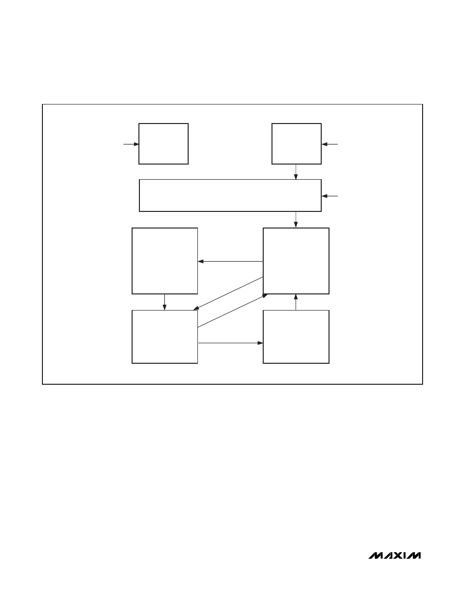
Figure 2. State Diagram
FAULT
TIMEOUT
(ASYNCHRONOUS
FROM ANYWHERE)
ERROR
ON = 1
P1, P2 = OFF
N1, N2 = ON
OFF
ON = 0
P1, P2 = OFF
N1, N2 = ON
I
Q
= 0
μA
ON = 0
(ASYNCHRONOUS
FROM
ANYWHERE)
REFOK = 0 OR
UVLO = 0
(ASYNCHRONOUS
FROM ANYWHERE)
PHASE 2
SLOW CHARGE/
DISCHARGE
OSC = ON
P1, P2 = ON
N1, N2 = OFF
PHASE 3
FAST DISCHARGE
OSC = ON
P2, N1 = ON
P1, N2 = OFF
PHASE 1
FAST-CHARGE
OSC = ON
P1, N2 = ON
P2, N1 = OFF
PHASE 4
HOLD
OSC = OFF
N1, N2 = ON
P1, P2 = OFF
POWER-UP
ON = 1, P1, P2 = OFF, N1, N2 = ON,
OSC = ON AND REF = ON IF UVLO OK
T2-3
T3-4
T1-2
T3-1
T1-3
T4-1
TRUN
TPUP
(SKIP)