Rainbow Electronics MAX5189 User Manual
Page 12
MAX5186/MAX5189
Dual, 8-Bit, 40MHz, Current/Voltage,
Simultaneous-Output DACs
12
______________________________________________________________________________________
I/Q Reconstruction in a QAM Application
The MAX5186/MAX5189’s low distortion supports ana-
log reconstruction of in-phase (I) and quadrature (Q)
carrier components typically used in quadrature ampli-
tude modulation (QAM) architectures where I and Q
data are interleaved on a common data bus. A QAM
signal is both amplitude and phase modulated, created
by summing two independently modulated carriers of
identical frequency but different phase (90° phase dif-
ference).
In a typical QAM application (Figure 7), the modulation
occurs in the digital domain and the MAX5186/
MAX5189’s dual DACs may be used to reconstruct the
analog I and Q components.
The I/Q reconstruction system is completed by a quad-
rature modulator that combines the reconstructed I and
Q components with in-phase and quadrature carrier
frequencies and then sums both outputs to provide the
QAM signal.
Grounding and Power-Supply Decoupling
Grounding and power-supply decoupling strongly influ-
ence the MAX5186/MAX5189’s performance. Unwanted
digital crosstalk may couple through the input, refer-
0
2
1
4
3
7
6
5
000
010
001
011
100
101
110
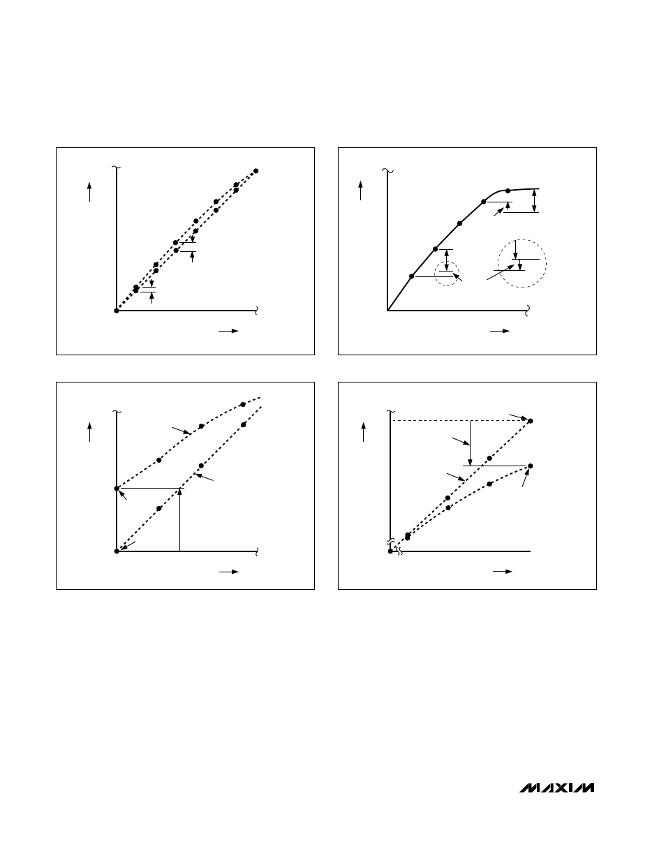
AT STEP
011 (1/2 LSB )
AT STEP
001 (1/4 LSB )
111
DIGITAL INPUT CODE
ANALOG OUTPUT VALUE
Figure 5a. Integral Nonlinearity
0
2
1
3
000
010
001
011
ACTUAL
DIAGRAM
IDEAL DIAGRAM
ACTUAL
OFFSET
POINT
OFFSET ERROR
(+1 1/4 LSB)
IDEAL OFFSET
POINT
DIGITAL INPUT CODE
ANALOG OUTPUT VALUE
Figure 5c. Offset Error
0
5
4
6
7
000
101
100
110
111
IDEAL DIAGRAM
GAIN ERROR
(-1 1/4 LSB)
IDEAL FULL-SCALE OUTPUT
ACTUAL
FULL-SCALE
OUTPUT
DIGITAL INPUT CODE
ANALOG OUTPUT VALUE
Figure 5d. Gain Error
0
2
1
4
3
6
5
000
010
001
011
100
101
DIFFERENTIAL LINEARITY
ERROR (-1/4 LSB)
DIFFERENTIAL
LINEARITY ERROR (+1/4 LSB)
1 LSB
1 LSB
DIGITAL INPUT CODE
ANALOG OUTPUT VALUE
Figure 5b. Differential Nonlinearity