Table 1. power-down mode selection – Rainbow Electronics MAX5189 User Manual
Page 11
MAX5186/MAX5189
Dual, 8-Bit, 40MHz, Current/Voltage,
Simultaneous-Output DACs
______________________________________________________________________________________
11
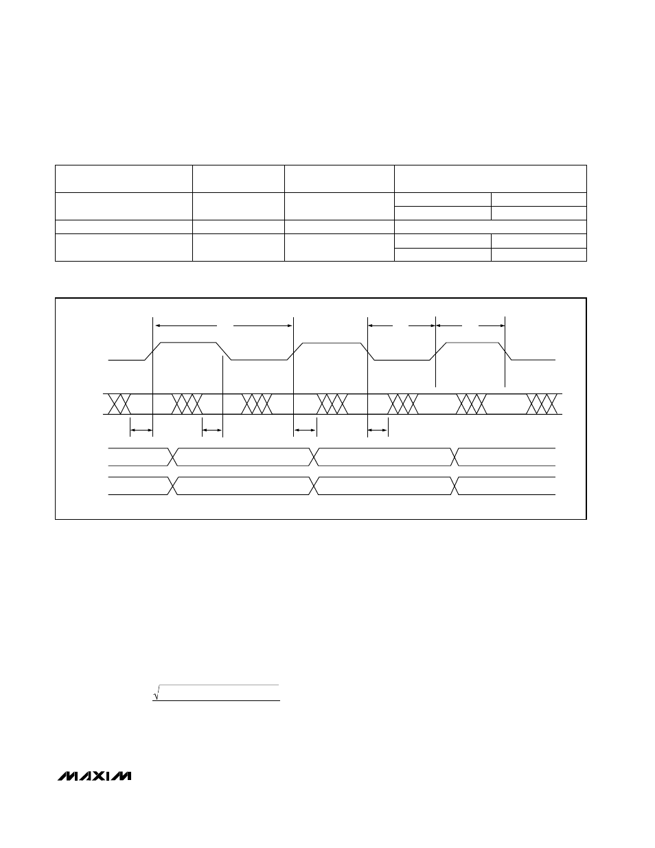
Figure 4. Timing Diagram
X = Don’t care
Table 1. Power-Down Mode Selection
CLK
D0–D7
OUT1
N - 2
DAC1
DAC1
DAC2
DAC2
DAC1
DAC2
N - 1
N
t
DS1
t
CH
t
CL
t
CLK
t
DS2
t
DH1
t
DH1
OUT2
N - 2
N - 1
N
Digital Feedthrough
Digital feedthrough is the noise generated on a DAC’s
output when any digital input transitions. Proper board
layout and grounding will significantly reduce this
noise, but there will always be some feedthrough
caused by the DAC itself.
Total Harmonic Distortion
Total harmonic distortion (THD) is the ratio of the RMS
sum of the input signal’s first four harmonics to the fun-
damental itself. This is expressed as:
where V
1
is the fundamental amplitude, and V
2
through
V
5
are the amplitudes of the 2nd- through 5th-order
harmonics.
Spurious-Free Dynamic Range
Spurious-free dynamic range (SFDR) is the ratio of RMS
amplitude of the fundamental (maximum signal compo-
nent) to the RMS value of the next largest distortion
component.
Differential to Single-Ended Conversion
The MAX4108 low-distortion, high-input bandwidth
amplifier may be used to generate a voltage from the
array current output of the MAX5186. The differential
voltage across OUT1P (or OUT2P) and OUT1N (or
OUT2N) is converted into a single-ended voltage by
designing an appropriate operational amplifier configu-
ration (Figure 6).
THD
20 log
(V
V
V
V
)
V
2
3
4
5
1
2
2
2
2
=
×
+
+
+
AGND
High-Z
AGND
High-Z
MAX5189
MAX5186
Shutdown
X
1
Last state prior to standby mode
Wake-Up
1
0
MAX5189
MAX5186
Standby
0
0
OUTPUT STATE
POWER-DOWN
MODE
DACEN (DAC
ENABLE)
PD
(POWER-DOWN SELECT)