Rainbow Electronics MAX5812 User Manual
Page 8
MAX5812
12-Bit Low-Power, 2-Wire, Serial
Voltage-Output DAC
8
_______________________________________________________________________________________
and a serial clock line (SCL). The MAX5812 is SMBus
compatible within the range of V
DD
= 2.7V to 3.6V. SDA
and SCL facilitate bidirectional communication between
the MAX5812 and the master at rates up to 400kHz.
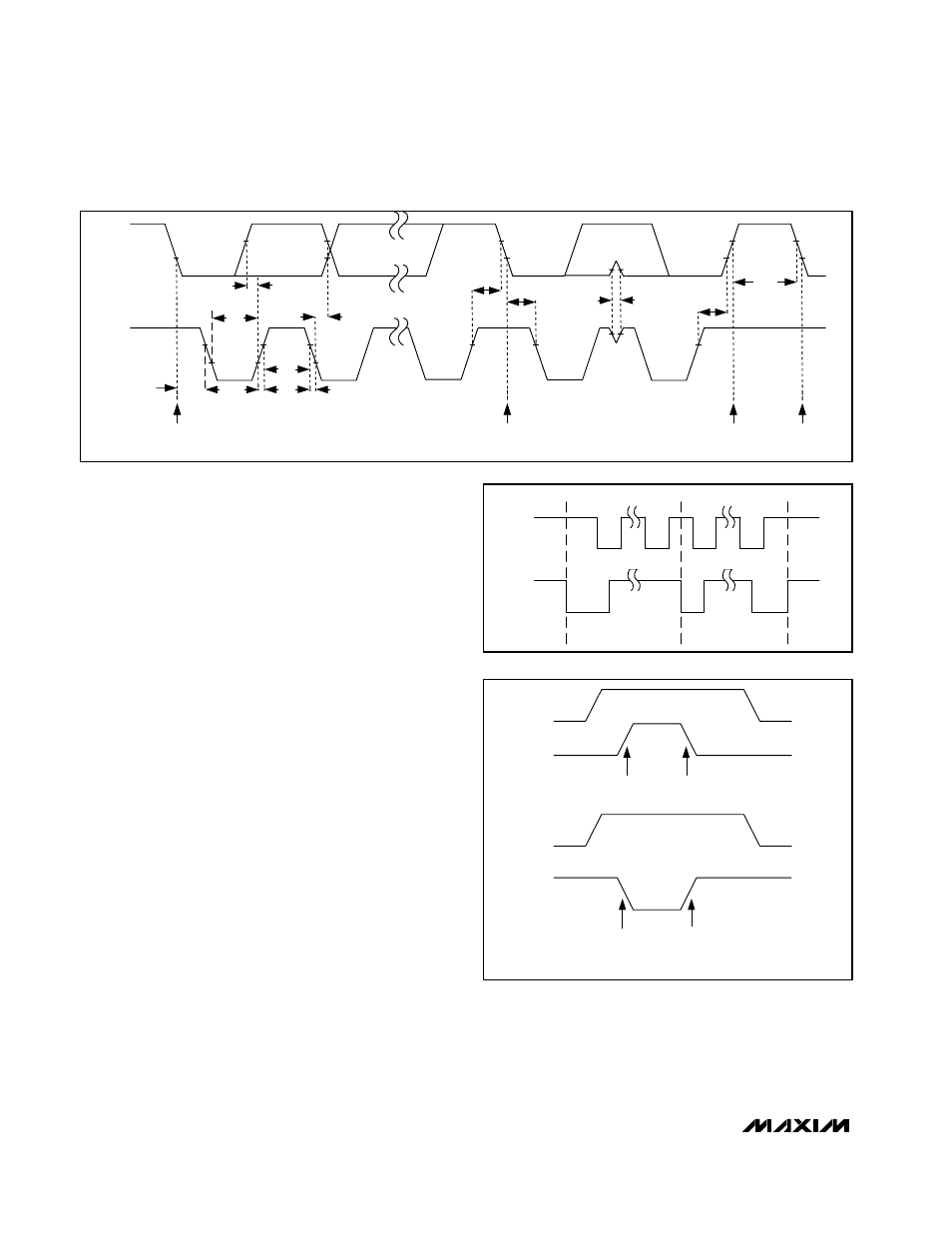
Figure 1 shows the 2-wire interface timing diagram. The
MAX5812 is a transmit/receive slave-only device, rely-
ing upon a master to generate a clock signal. The mas-
ter, typically a microcontroller, initiates data transfer on
the bus and generates SCL to permit that transfer.
A master device communicates to the MAX5812 by
transmitting the proper address followed by command
and/or data words. Each transmit sequence is framed
by a START (S) or REPEATED START (S
r
) condition and
a STOP (P) condition. Each word transmitted over the
bus is 8 bits long and is always followed by an
acknowledge clock pulse.
The MAX5812 SDA and SCL drivers are open-drain out-
puts, requiring a pullup resistor (500
Ω or greater) to
generate a logic high voltage (see the Typical Operating
Circuit). Series resistors R
S
are optional. These series
resistors protect the input stages of the MAX5812 from
high-voltage spikes on the bus lines and minimize
crosstalk and undershoot of the bus signals.
Bit Transfer
One data bit is transferred during each SCL clock
cycle. The data on SDA must remain stable during the
high period of the SCL clock pulse. Changes in SDA
while the SCL is high are control signals (see the
START and STOP Conditions section). SDA and SCL
idle high when the I
2
C bus is not busy.
START and STOP Conditions
When the serial interface is inactive, SDA and SCL idle
high. A master device initiates communication by issu-
ing a START condition. A START condition is a high-to-
Figure 1. Two-Wire Serial lnterface Timing Diagram
SCL
SDA
STOP
CONDITION
START
CONDITION
REPEATED START CONDITION
START CONDITION
t
LOW
t
SU, DAT
t
SU, STA
t
SP
t
BUF
t
HD, STA
t
SU, STO
t
R
tF
t
HD, STA
t
HIGH
t
HD, DAT
SCL
SDA
S
Sr
P
Figure 2. START/STOP Conditions
Figure 3. Early STOP condition
SCL
SDA
STOP
START
SCL
SDA
ILLEGAL
STOP
START
ILLEGAL EARLY STOP CONDITION
LEGAL STOP CONDITION