Applications information – Rainbow Electronics MAX8562 User Manual
Page 7
MAX8560/MAX8561/MAX8562
4MHz, 500mA Synchronous Step-Down
DC-DC Converters in SOT and TDFN
_______________________________________________________________________________________
7
Shutdown Mode
Connecting SHDN to GND or logic low places the
MAX8560/MAX8561/MAX8562 in shutdown mode and
reduces supply current to 0.1µA. In shutdown, the con-
trol circuitry, internal-switching P-channel MOSFET, and
synchronous rectifier (N-channel MOSFET) turn off and
LX becomes high impedance. Connect SHDN to IN or
logic high for normal operation.
Soft-Start
The MAX8560/MAX8561/MAX8562 have internal soft-
start circuitry that eliminates inrush current at startup,
reducing transients on the input source. Soft-start is par-
ticularly useful for higher impedance input sources,
such as Li+ and alkaline cells. See the Soft-Start and
Shutdown Response graphs in the Typical Operating
Characteristics section.
Open-Drain Output
The 8-pin TDFN versions, the MAX8561 and MAX8562,
include an extra, internal, open-drain N-channel MOSFET
switch that can save an additional package in space-con-
strained applications. The open drain is connected to
ODO, while the gate is controlled by a digital input at
ODI. For the MAX8561, this circuit can be used to toggle
between two regulated output voltages, as in Figure 2.
For the MAX8562, a 10k
Ω resistor pulls ODO up to IN
when ODI is low, and the buck converter is forced into
100% duty cycle when ODI is high. This makes the
MAX8562 ideal for driving an external bypass PFET for
high-power mode in CDMA cell phones, as in Figure 3.
Applications Information
The MAX8560/MAX8561/MAX8562 are optimized for
use with tiny inductors and small ceramic capacitors.
The correct selection of external components, especial-
ly C
FF
, ensures high efficiency, low output ripple, and
fast transient response.
Setting the Output Voltage
Select an output voltage between 0.6V and 2.5V by
connecting FB to a resistive voltage-divider between LX
and GND (see the Typical Operating Circuit). Choose
R2 for a reasonable bias current in the resistive divider.
A wide range of resistor values is acceptable, but a
good starting point is to choose R2 as 100k
Ω. Then, R1
is given by:
where V
FB
= 0.6V.
Inductor Selection
The MAX8560/MAX8561/MAX8562 operate with inductors
of 1µH to 4.7µH. Low inductance values are smaller but
require faster switching, which results in some efficiency
loss. See the Typical Operating Characteristics section
for efficiency and switching frequency vs. inductor value.
The inductor’s DC current rating only needs to match the
maximum load current of the application + 50mA
because the MAX8560/MAX8561/ MAX8562 feature zero
current overshoot during startup and load transients.
For output voltages above 2.0V, when light-load efficien-
cy is important, the minimum recommended inductor is
2.2µH. For optimum voltage-positioning load transients,
choose an inductor with DC series resistance in the
50m
Ω to 150mΩ range. For higher efficiency at heavy
loads (above 200mA) or minimal load regulation (but
some transient overshoot), the resistance should be kept
below 100m
Ω. For light-load applications up to 200mA,
much higher resistance is acceptable with very little
impact on performance.
R
R
V
V
OUT
FB
1
2
1
=
−
FB
LX
IN
0.6V
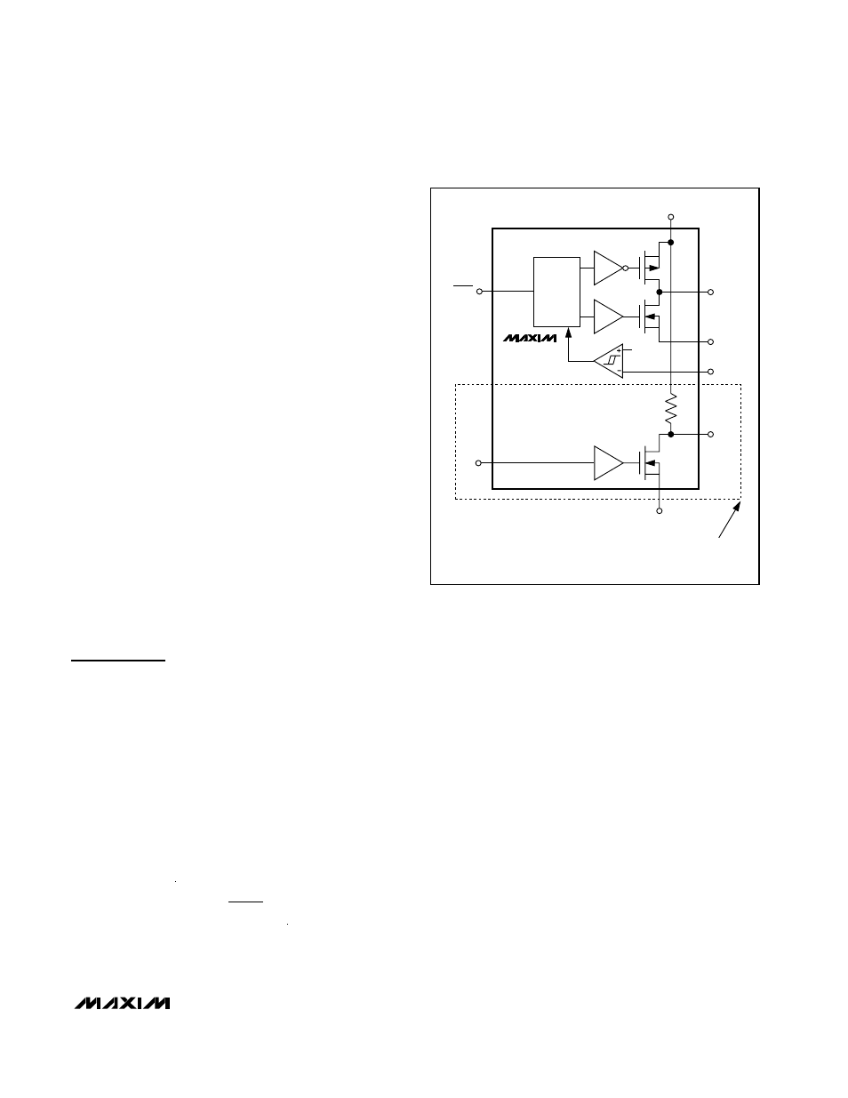
MAX8560
MAX8561*
MAX8562*
ODO
*NOTE: ODI/ODO AVAILABLE IN THE MAX8561/MAX8562 ONLY.
THE MAX8561 ODO IS AN OPEN-DRAIN OUTPUT. THE MAX8562
HAS AN INTERNAL 10k
Ω PULLUP TO IN.
ODI
10k
Ω
GND
PGND
SHDN
PWM
LOGIC
PFET
NFET
Figure 1. Simplified Functional Diagram