Table 3. fault queue register bit definition (22h), Table 4. fault queue length bit definition – Rainbow Electronics MAX6649 User Manual
Page 9
MAX6649
+145°C Precision SMBus-Compatible Remote/
Local Sensor with Overtemperature Alarms
_______________________________________________________________________________________
9
interrupt latch, provided the condition that caused the
alert no longer exists.
OVERT
Overtemperature Alarm/Warning
Outputs
OVERT asserts when the temperature rises to a value
stored in one of the OVERT limit registers (19h, 20h). It
deasserts when the temperature drops below the
stored limit, minus hysteresis. OVERT can be used to
activate a cooling fan, send a warning, invoke clock
throttling, or trigger a system shutdown to prevent com-
ponent damage.
Command Byte Functions
The 8-bit command byte register (Table 5) is the master
index that points to the various other registers within the
MAX6649. The register’s POR state is 0000 0000, so a
receive byte transmission (a protocol that lacks the
command byte) that occurs immediately after POR,
returns the current local temperature data.
The MAX6649 incorporates collision avoidance so that
completely asynchronous operation is allowed between
SMBus operations and temperature conversions.
One-Shot
The one-shot command immediately forces a new con-
version cycle to begin. If the one-shot command is
received while the MAX6649 is in standby mode (RUN
bit = 1), a new conversion begins, after which the
device returns to standby mode. If a one-shot conver-
sion is in progress when a one-shot command is
received, the command is ignored. If a one-shot com-
mand is received in autonomous mode (RUN bit = 0)
between conversions, a new conversion begins, the
conversion rate timer is reset, and the next automatic
conversion takes place after a full delay elapses.
Configuration Byte Functions
The configuration byte register (Table 6) is a read-write
register with several functions. Bit 7 is used to mask (dis-
able) interrupts. Bit 6 puts the MAX6649 into standby
mode (STOP) or autonomous (RUN) mode.
Status Byte Functions
The status byte register (Table 7) indicates which (if
any) temperature thresholds have been exceeded. This
byte also indicates whether the ADC is converting and
whether there is an open-circuit fault detected in the
external sense junction. After POR, the normal state of
all flag bits is zero, assuming no alarm conditions are
present. The status byte is cleared by any successful
read of the status byte, after conversion is complete
and if the fault condition no longer exists. Note that the
ALERT interrupt latch is not automatically cleared when
the status flag bit indicating the ALERT is cleared. The
fault condition must be eliminated before the ALERT
output can be cleared.
When autoconverting, if the T
HIGH
and T
LOW
limits are
close together, it is possible for both high-temp and
low-temp status bits to be set, depending on the
amount of time between status read operations (espe-
cially when converting at the fastest rate). In these cir-
cumstances, it is best not to rely on the status bits to
indicate reversals in long-term temperature changes.
Instead use a current temperature reading to establish
the trend direction.
Conversion Rate Byte
The conversion rate register (Table 8) programs the
time interval between conversions in free-running
autonomous mode (RUN = 0). This variable rate control
can be used to reduce the supply current in portable-
equipment applications. The conversion rate byte’s
POR state is 07h or 4Hz. The MAX6649 looks only at
the 3 LSBs of this register, so the upper 5 bits are don’t
care bits, which should be set to zero. The conversion
rate tolerance is ±25% at any rate setting.
BIT
NAME
POR
STATE
FUNCTION
7
RFU
1
Reserved. Always write 1 to
this bit.
6 to 3
RFU
0
Reserved. Always write
zero to this bit.
2
FQ1
1
Fault queue-length control
bit (see Table 4).
1
FQ0
1
Fault queue-length control
bit (see Table 4).
0
RFU
0
Reserved. Always write
zero to this bit.
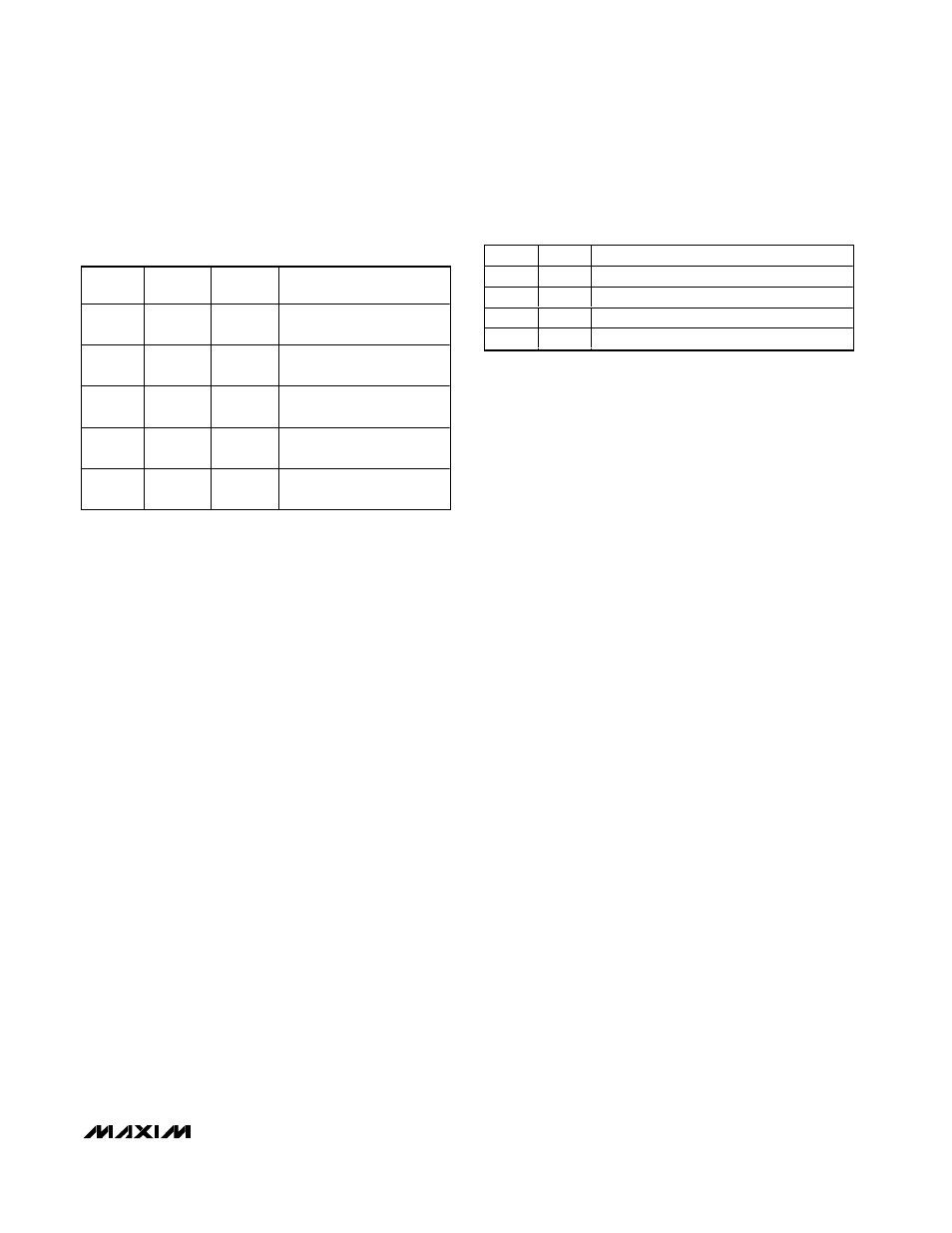
Table 3. Fault Queue Register Bit Definition
(22h)
FQ1
FQ0
FAULT QUEUE LENGTH (SAMPLES)
0
0
1
0
1
2
1
1
3
1
0
1
Table 4. Fault Queue Length Bit Definition