Alert – Rainbow Electronics MAX6649 User Manual
Page 8
MAX6649
+145°C Precision SMBus-Compatible Remote/
Local Sensor with Overtemperature Alarms
8
_______________________________________________________________________________________
The POR state of both ALERT T
HIGH
registers is full
scale (0101 0101, or +85°C). The POR state of both
T
LOW
registers is 0000 0000, or 0°C.
Two additional registers store remote and local alarm
threshold data corresponding to the OVERT output. The
values stored in these registers are high-temperature
thresholds. If either of the measured temperatures
equals or exceeds the corresponding alarm threshold
value, an OVERT output asserts. The POR state of the
OVERT threshold is 0101 0101 or +85°C.
Diode Fault Alarm
A continuity fault detector at DXP detects an open cir-
cuit between DXP and DXN, or a DXP short to V
CC
,
GND, or DXN. If an open or short circuit exists, the
external temperature register is loaded with 1111 1111.
If the fault is an open-circuit fault bit 2 (OPEN), the sta-
tus byte is set to 1 and the ALERT condition is activated
at the end of the conversion. Immediately after POR,
the status register indicates that no fault is present. If a
fault is present upon power-up, the fault is not indicated
until the end of the first conversion.
ALERT
Interrupts
The ALERT interrupt occurs when the internal or exter-
nal temperature reading exceeds a high- or low-tem-
perature limit (user programmed) or when the remote
diode is disconnected (for continuity fault detection).
The ALERT interrupt output signal is latched and can
be cleared only by either reading the status register or
by successfully responding to an alert response
address. In both cases, the alert is cleared if the fault
condition no longer exists. Asserting ALERT does not
halt automatic conversion. The ALERT output pin is
open drain, allowing multiple devices to share a com-
mon interrupt line.
The MAX6649 responds to the SMBus alert response
address, an interrupt pointer return-address feature
(see the Alert Response Address section). Prior to tak-
ing corrective action, always check to ensure that an
interrupt is valid by reading the current temperature.
Fault Queue Register
In some systems, it may be desirable to ignore a single
temperature measurement that falls outside the ALERT
limits. Bits 2 and 3 of the fault queue register (address
22h) determine the number of consecutive temperature
faults necessary to set ALERT (see Tables 3 and 4).
Alert Response Address
The SMBus alert response interrupt pointer provides
quick fault identification for simple slave devices that
lack the complex, expensive logic needed to be a bus
master. Upon receiving an ALERT interrupt signal, the
host master can broadcast a receive byte transmission
to the alert response slave address (0001 100).
Following such a broadcast, any slave device that gen-
erated an interrupt attempts to identify itself by putting
its own address on the bus.
The alert response can activate several different slave
devices simultaneously, similar to the I
2
C™ general call.
If more than one slave attempts to respond, bus arbitra-
tion rules apply, and the device with the lower address
code wins. The losing device does not generate an
acknowledge and continues to hold the ALERT line low
until cleared. (The conditions for clearing an ALERT vary,
depending on the type of slave device). Successful com-
pletion of the read alert response protocol clears the
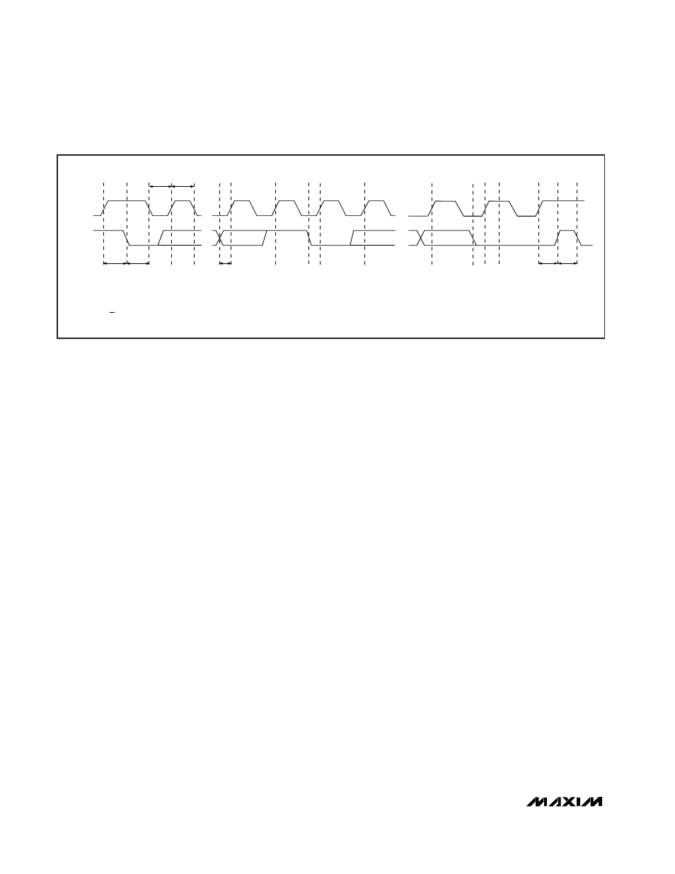
SMBCLK
A = START CONDITION
B = MSB OF ADDRESS CLOCKED INTO SLAVE
C = LSB OF ADDRESS CLOCKED INTO SLAVE
D = R/W BIT CLOCKED INTO SLAVE
A
B
C
D
E
F
G
H
I
J
SMBDATA
t
SU:STA
t
HD:STA
t
LOW
t
HIGH
t
SU:DAT
t
SU:STO
t
BUF
L
M
K
E = SLAVE PULLS SMBDATA LINE LOW
F = ACKNOWLEDGE BIT CLOCKED INTO MASTER
G = MSB OF DATA CLOCKED INTO SLAVE
H = LSB OF DATA CLOCKED INTO SLAVE
I = MASTER PULLS DATA LINE LOW
J = ACKNOWLEDGE CLOCKED INTO SLAVE
K = ACKNOWLEDGE CLOCK PULSE
L = STOP CONDITION
M = NEW START CONDITION
Figure 3. SMBus Read Timing Diagram
I
2
C is a trademark of Philips Corp.