Rainbow Electronics MAX6649 User Manual
Page 7
MAX6649
+145°C Precision SMBus-Compatible Remote/
Local Sensor with Overtemperature Alarms
_______________________________________________________________________________________
7
registers. If no conversion is in progress, the data
can be read within a few microseconds, which is a
sufficiently short period of time to ensure that a new
conversion cannot be completed until after the data
has been read.
Alarm Threshold Registers
Four registers store ALERT threshold values—one high-
temperature (T
HIGH
) and one low-temperature (T
LOW
)
register each for the local and remote channels. If
either measured temperature equals or exceeds the
corresponding ALERT threshold value, the ALERT inter-
rupt asserts.
SMBCLK
A
B
C
D
E
F
G
H
I
J
K
SMBDATA
t
SU:STA
t
HD:STA
t
LOW
t
HIGH
t
SU:DAT
t
HD:DAT
t
SU:STO
t
BUF
A = START CONDITION
B = MSB OF ADDRESS CLOCKED INTO SLAVE
C = LSB OF ADDRESS CLOCKED INTO SLAVE
D = R/W BIT CLOCKED INTO SLAVE
E = SLAVE PULLS SMBDATA LINE LOW
L
M
F = ACKNOWLEDGE BIT CLOCKED INTO MASTER
G = MSB OF DATA CLOCKED INTO MASTER
H = LSB OF DATA CLOCKED INTO MASTER
I = MASTER PULLS DATA LINE LOW
J = ACKNOWLEDGE CLOCKED INTO SLAVE
K = ACKNOWLEDGE CLOCK PULSE
L = STOP CONDITION
M = NEW START CONDITION
Figure 2. SMBus Write Timing Diagram
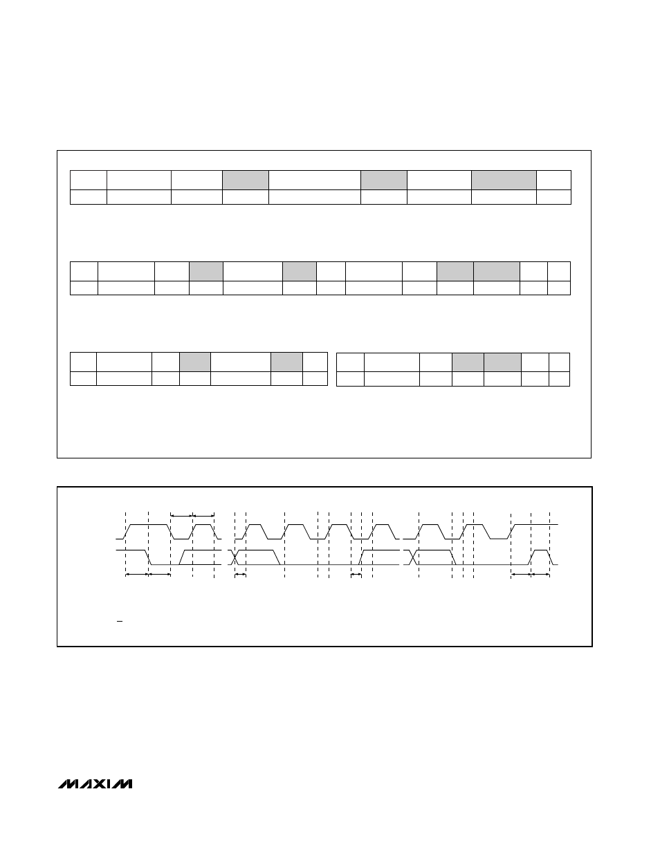
Write Byte Format
Read Byte Format
Send Byte Format
Receive Byte Format
Slave Address: equiva-
lent to chip-select line of
a 3-wire interface
Command Byte: selects which
register you are writing to
Data Byte: data goes into the register
set by the command byte (to set
thresholds, configuration masks, and
sampling rate)
Slave Address: equiva-
lent to chip-select line
Command Byte: selects
which register you are
reading from
Slave Address: repeated
due to change in data-
flow direction
Data Byte: reads from
the register set by the
command byte
Command Byte: sends com-
mand with no data, usually
used for one-shot command
Data Byte: reads data from
the register commanded
by the last Read Byte or
Write Byte transmission;
also used for SMBus Alert
Response return address
S = Start condition
Shaded = Slave transmission
P = Stop condition
/// = Not acknowledged
Figure 1. SMBus Protocols
S
ADDRESS
WR
ACK
COMMAND
7 bits
8 bits
ACK
DATA
8 bits
ACK
P
1
S
ADDRESS
WR
ACK
COMMAND
ACK
S
ADDRESS
RD
ACK
DATA
///
P
8 bits
7 bits
8 bits
7 bits
S
ADDRESS
WR
ACK
COMMAND
ACK
P
7 bits
8 bits
S
ADDRESS
RD
ACK
DATA
///
P
8 bits
7 bits