Pin description – Rainbow Electronics MAX6681 User Manual
Page 5
MAX6680/MAX6681
±1°C Fail-Safe Remote/Local Temperature
Sensors with SMBus Interface
_______________________________________________________________________________________
5
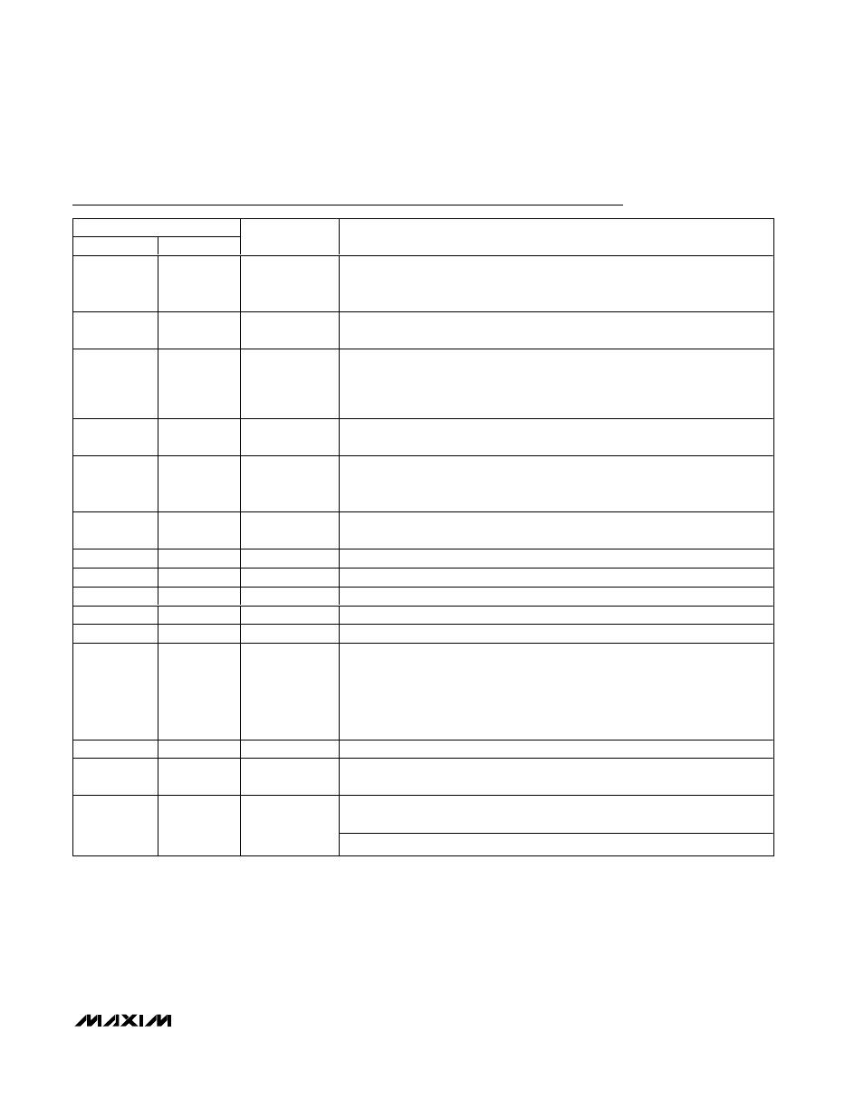
Pin Description
PIN
MAX6680
MAX6681
NAME
FUNCTION
1
2
V
CC
Supply Voltage Input, 3V to 5.5V. Bypass V
CC
to GND with a 0.1µF capacitor.
A 200
Ω series resistor is recommended, but not required for additional noise
filtering. See the Typical Operating Circuit.
2, 5
1, 5
CRIT1,
CRIT0
Hardware-Programmable Default Alarm Threshold for
OVERT Limits. Use Table
4 to set default temperatures.
3
3
DXP
Combined Remote-Diode Current Source and A/D Positive Input for Remote-
Diode Channel. DO NOT LEAVE DXP FLOATING; connect DXP to DXN if no
remote diode is used. Place a 2200pF capacitor between DXP and DXN for
noise filtering.
4
4
DXN
Combined Remote-Diode Current Sink and A/D Negative Input. DXN is
internally biased to one diode drop above ground.
6
6
ADD1
SMBus Address Select Pin (Table 9). ADD0 and ADD1 are sampled upon
power-up. Excess capacitance (>50pF) at the address pins when floating may
cause address-recognition problems.
7
7
RESET
Reset Input. Drive RESET high to set all registers to their default values (POR
state). Drive RESET low or leave floating for normal operation.
8
8
GND
Ground
9
9
OVERT
Overtemperature Active-Low Output. Open drain.
10
10
ADD0
SMBus Slave Address Select Pin (see ADD1).
11
11
ALERT
SMBus Alert (Interrupt) Active-Low Output. Open drain.
12
12
SMBDATA
SMBus Serial-Data Input/Output, Open Drain
13
13
INT_SEL
Input. Connect high or leave floating to conform to the standard SMBus
ALERT
protocol. See the
ALERT
Interrupts section. Connect to GND to invoke
comparator mode, where
ALERT is asserted whenever any of the temperature
conditions is violated by the remote sensor. In this mode,
ALERT can only be
deasserted by the condition returning within the temperature limits by enabling
the mask bit in the Configuration register.
14
14
SMBCLK
SMBus Serial-Clock Input
15
15
STBY
Input. Hardware Standby. Connect to ground to place in device in standby.
Supply current drops below 10µA and all registers’ data are maintained.
Input. Selects which temperature sensor (local, remote, or both) activates
OVERT.
16
16
SENS_SEL
High = Local, Low = Remote, Open = Local and Remote