Table 6. configuration-byte bit assignment, Table 7. status register bit assignments – Rainbow Electronics MAX6681 User Manual
Page 14
MAX6680/MAX6681
autonomous mode (RUN/STOP = 0). This variable rate
control can be used to reduce the supply current in
portable-equipment applications. The conversion rate
byte’s POR state is 02h (0.25Hz). The MAX6680/
MAX6681 use only the 3LSBs of this register. The
5MSBs are “don’t care” and should be set to zero when
possible. The conversion rate tolerance is ±25% at any
rate setting.
Valid A/D conversion results for both channels are avail-
able one total conversion time (125ms nominal, 156ms
maximum) after initiating a conversion, whether conver-
sion is initiated through the RUN/STOP bit, hardware
STBY pin, One-Shot command, or initial power-up.
Slave Addresses
The MAX6680/MAX6681 device address can be initially
set to nine different values by pin strapping ADD0 and
ADD1 so that more than one MAX6680/MAX6681 can
±1°C Fail-Safe Remote/Local Temperature
Sensors with SMBus Interface
14
______________________________________________________________________________________
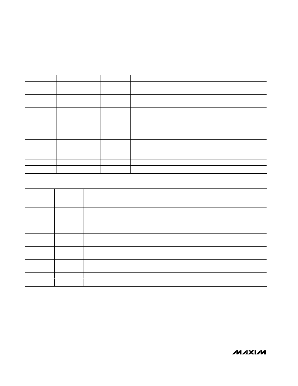
BIT
NAME
POR STATE
FUNCTION
7 (MSB)
ALERT MASK
0
Mask
ALERT active state when 1. When 1, ALERT does not respond to
any fault related to the four limit registers.
6
RUN/STOP
0
Standby mode control bit; if 1, immediately stops converting and enters
standby mode. If zero, it converts in either one-shot or timer mode.
5
SPNP
1
When 1, the remote sensor is a common-collector substrate PNP. When
zero, the remote sensor is a diode-connected transistor.
4
Extended Resolution
0
When zero, remote- and local-sensors’ temperature data are 7 bits +
sign with 1°C resolution. When 1, the remote-sensor temperature data is
10 bits + sign with 0.125°C resolution.
3
Extended Range
0
Extended temperature range. 0 = normal, 1 = extended to -64°C.
2
SMBus Timeout
0
When set to 1, it disables the SMBus timeout, as well as the alert
response.
1
Software Reset
0
Software reset from SMBus from customer.
0
RFU
0
Reserved
Table 6. Configuration-Byte Bit Assignment
BIT
NAME
POR
STATE
FUNCTION
7 (MSB)
BUSY
0
When 1, the A/D is busy converting.
6
LHIGH
0
When 1, internal high-temperature alarm has tripped; cleared by POR or readout
of the Status register, if the fault condition no longer exists.
5
LLOW
0
When 1, internal low-temperature alarm has tripped; cleared by POR or readout of
the Status register, if the fault condition no longer exists.
4
RHIGH
0
When 1, external high-temperature alarm has tripped; cleared by POR or readout
of the Status register, if the fault condition no longer exists.
3
RLOW
0
When 1, external low-temperature alarm has tripped; cleared by POR or readout of
the Status register if the fault condition no longer exists.
2
OPEN
0
When 1 indicates an external diode open; cleared by POR or readout of the Status
register, if the fault condition no longer exists.
1
OVI
0
When 1, internal temperature exceeds the RWOI limit.
0
OVE
0
When 1, external temperature exceeds the RWOE limit.
Table 7. Status Register Bit Assignments