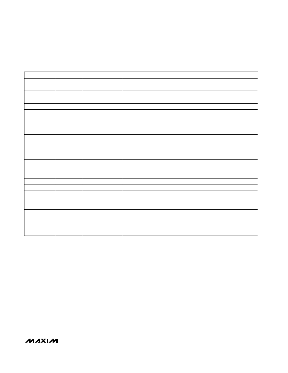
Table 5. command-byte register bit assignments – Rainbow Electronics MAX6681 User Manual
Page 13
still exists, they are reasserted at the end of the next
conversion. If the MAX6680/MAX6681 are operating in
the comparator mode, bits 2–6 of the Status register
are cleared only after the local and/or remote tempera-
tures return within the set limits.
The bits indicating OVTI and OVTE are cleared only
when the condition no longer exists. Reading the status
byte does not clear the OVERT output or fault bits. One
way to eliminate the fault condition is for the measured
temperature to drop below the temperature threshold
minus the hysteresis value. Another way to eliminate
the fault condition is by writing new values for the
RWOI, RWOE, or HYST registers so that a fault condi-
tion is no longer present.
The MAX6680/MAX6681 incorporate collision avoid-
ance so that completely asynchronous operation is
allowed between SMBus operations and temperature
conversions.
When autoconverting, if the T
HIGH
and T
LOW
limits are
close together, it is possible for both high-temp and
low-temp status bits to be set, depending on the
amount of time between status read operations. In
these circumstances, it is best not to rely on the status
bits to indicate reversals in long-term temperature
changes. Instead use a current temperature reading to
establish the trend direction.
Hardware/Software Reset
The MAX6680/MAX6681 reset at power-on if pin 7 is
taken high, or by software reset through bit 1 of the
Configuration register. When reset occurs, all registers
go to default values, and the SMBus address pins are
sampled.
Conversion Rate Byte
The Conversion Rate register (Table 8) programs the
time interval between conversions in free-running
MAX6680/MAX6681
±1°C Fail-Safe Remote/Local Temperature
Sensors with SMBus Interface
______________________________________________________________________________________
13
REGISTER
ADDRESS
POR STATE
FUNCTION
RLTS
00h
0000
at 0°C
Read Internal Temperature
RRTE
01h
0000
(0°C)
Read External Temperature
RSL
02h
0000 0000
Read Status Register
RCL/WCL
03h/09h
0010 0000
Read/Write Configuration Byte
RCRA/WCRA
04h/0A
0000 0010
Read/Write Conversion Rate Byte
RIH/WIH
05h/0Bh
0111 1111
(+127°C)
Read/Write Internal
ALERT High Limit
RIL/WIL
06h/0Ch
1100 1001
( -55°C)
Read/Write Internal
ALERT Low Limit
REH/WEH
07h/0Dh
0100 0110
(+127°C)
Read/Write External
ALERT High Limit
REL/WEL
08h/0Eh
1100 1001
(-55°C)
Read/Write External
ALERT Low Limit
OSHT
0Fh
0000
One Shot
REET
10h
0000 0000
Read External Extended Temperature
RWOH
11h
0000 0000
Read/Write External Offset High Byte
RWOL
12h
0000 0000
Read/Write External Offset Low Byte
RWOE
19h
See Table 4
Read/Write External
OVERT Limit
RWOI
20h
See Table 4
Read/Write Internal
OVERT Limit
HYST
21h
0000 0110
(+6°C)
OVERT Hysteresis
RDID
FEh
0100 1101
Read Manufacturer ID
RDRV
Ff
0000 0001
Read Device Revision
Table 5. Command-Byte Register Bit Assignments