Electrical characteristics (continued) – Rainbow Electronics MAX6681 User Manual
Page 3
MAX6680/MAX6681
±1°C Fail-Safe Remote/Local Temperature
Sensors with SMBus Interface
_______________________________________________________________________________________
3
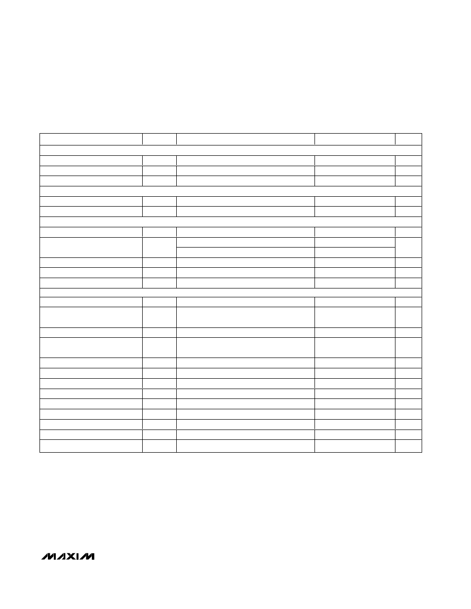
ELECTRICAL CHARACTERISTICS (continued)
(Circuit of Typical Operating Circuit, V
CC
= 3.0V to 5.5V, T
A
= -25°C to +125°C, unless otherwise specified. Typical values are at V
CC
= 3.3V and T
A
= +25°C.)
Note 1: T
A
= +25°C to +85°C.
Note 2: If both the local and the remote junction are below T
A
= -20°C, then V
CC
> 3.15V.
Note 3: Conversions done in extended mode. For legacy mode, current is approximately half.
Note 4: Timing specifications guaranteed by design.
Note 5: The serial interface resets when SMBCLK or SMBDATA is low for more than t
TIMEOUT
.
Note 6: A transition must internally provide at least a hold time to bridge the undefined region (300ns max) of SMBCLK’s falling edge.
PARAMETER
SYMBOL
CONDITIONS
MIN
TYP
MAX
UNITS
CRIT0, CRIT1, ADD0, ADD1, RESET, INT_SEL, SENS_SEL
Logic Input Low Voltage
V
IL
0.8
V
Logic Input High Voltage
V
IH
2.4
V
Input Leakage Current
I
LEAK
-1
+1
µA
(ALERT, OVERT)
Output Low Sink Current
V
OL
= 0.4V
1
mA
Output High Leakage Current
V
OH
= 5.5V
1
µA
SMBus INTERFACE (SMBCLK, SMBDATA, STBY)
Logic Input Low Voltage
V
IL
0.8
V
V
CC
= 3.0V
2.2
Logic Input High Voltage
V
IH
V
CC
= 5.5V
2.4
V
Input Leakage Current
I
LEAK
V
IN
= GND or V
CC
±2
µA
Output Low Sink Current
I
OL
V
OL
= 0.6V
6
mA
Input Capacitance
C
IN
5
pF
SMBus-COMPATIBLE TIMING (Note 5)
Serial Clock Frequency (Note 5)
f
SCL
100
kHz
Bus Free Time Between STOP
and START Condition
t
BUF
4.7
µs
START Condition Setup Time
4.7
µs
Repeat START Condition Setup
Time
t
SU:STA
90% to 90%
50
ns
START Condition Hold Time
t
HD:STA
10% of SMBDATA to 90% of SMBCLK
4
µs
STOP Condition Setup Time
t
SU:STO
90% of SMDCLK to 90% of SMBDATA
4
µs
Clock Low Period
t
LOW
10% to 10%
4.7
µs
Clock High Period
t
HIGH
90% to 90%
4
µs
Data Setup Time (Note 6)
t
HD:DAT
250
ns
Receive SCL/SDA Rise Time
t
R
1
µs
Receive SCL/SDA Fall Time
t
F
300
ns
Pulse Width of Spike Suppressed
t
SP
0
50
ns
SMBus Timeout (Note 5)
SMBDATA low period for interface reset
25
37
45
ms