Daisy-chaining devices – Rainbow Electronics MAX5121 User Manual
Page 16
TO OTHER
SERIAL DEVICES
MAX5120
MAX5121
DIN
SCLK
CS
MAX5120
MAX5121
MAX5120
MAX5121
DIN
DOUT
DOUT
DOUT
SCLK
CS
I
II
III
DIN
SCLK
CS
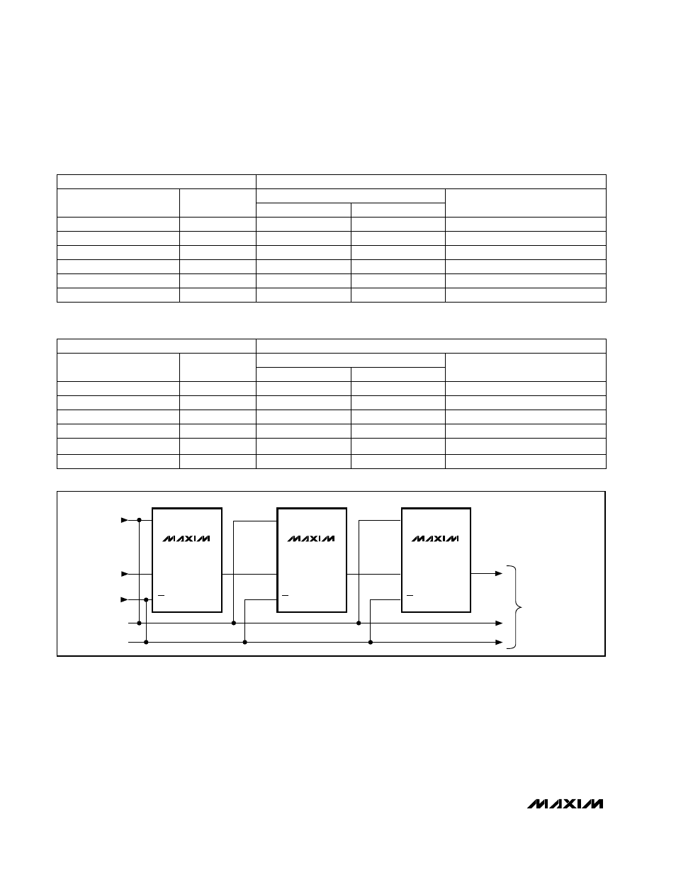
Figure 12. Daisy-Chaining Multiple Devices with the Digital I/Os DIN/DOUT
MAX5120/MAX5121
Daisy-Chaining Devices
Any number of MAX5120/MAX5121s can be daisy-
chained simply by connecting the serial data output pin
(DOUT) of one device to the digital input pin (DIN) of
the following device in the chain (Figure 12).
Another configuration allows several MAX5120/
MAX5121 DACs to share one common DIN signal line
(Figure 13). In this configuration, the data bus is com-
mon to all devices; data is not shifted through a daisy-
chain. However, more I/O lines are required in this
configuration, because each IC needs a dedicated CS
line.
+3V/+5V, 12-Bit, Serial Voltage-Output DACs
with Internal Reference
16
______________________________________________________________________________________
+V
REF
(2049 / 4096)
·
1.6384
1000 0000 0001
+2.049V
+4.0950V
+1.0245V
+2.0475V
+V
REF
(2047 / 4096)
·
1.6384
0111 1111 1111
+2.047V
+2.048V
+1.0235V
+1.024V
+V
REF
(2048 / 4096)
·
1.6384
1000 0000 0000
0V
0000 0000 0000
0V
+1mV
0V
+0.5mV
+V
REF
(4095 / 4096)
·
1.6384
1111 1111 1111
ANALOG OUTPUT
+V
REF
(1 / 4096)
·
1.6384
0000 0000 0001
INTERNAL REFERENCE
MSB LSB
MAX5120
MAX5121
EXTERNAL REFERENCE
V
REF
·
[ {2 · (2049 / 4096)} - 1]
1000 0000 0001
+1.2207mV
+2.49878V
+610.35µV
+1.24939V
MSB LSB
V
REF
·
[ {2 · (2047 / 4096)} - 1]
0111 1111 1111
-1.2207µV
0V
-610.35µV
0V
MAX5120
V
REF
·
[ {2 · (2048 / 4096)} - 1]
1000 0000 0000
MAX5121
-V
REF
0000 0000 0000
-2.5V
-2.49878V
-1.25V
-1.24939V
EXTERNAL REFERENCE
V
REF
·
[ {2 · (4095 / 4096)} - 1]
1111 1111 1111
ANALOG OUTPUT
V
REF
·
[ {2 · (14096)} - 1]
0000 0000 0001
INTERNAL REFERENCE
Table 5. Unipolar Code Table (Gain = 1.6384V/V)
Table 6. Bipolar Code Table for Figure 11
0
SUB-BIT
S0
0
0
0
0
0
DAC CONTENTS
0
SUB-BIT
SO
0
0
0
0
0
DAC CONTENTS