Table 1. serial-interface programming commands – Rainbow Electronics MAX5121 User Manual
Page 11
Power-Down Lockout Input (
PDL
)
The power-down lockout pin (PDL) disables shutdown
when low. When in shutdown mode, a high-to-low tran-
sition on PDL will wake up the DAC with its output still
set to the state prior to power-down. PDL can also be
used to wake up the device asynchronously.
Power-Down Input (PD)
Pulling PD high places the MAX5120/MAX5121 in shut-
down mode. Pulling PD low will not return the MAX5120/
MAX5121 to normal operation. A high-to-low transition
on PDL or appropriate commands (Table 1) via the seri-
al interface are required to exit power-down.
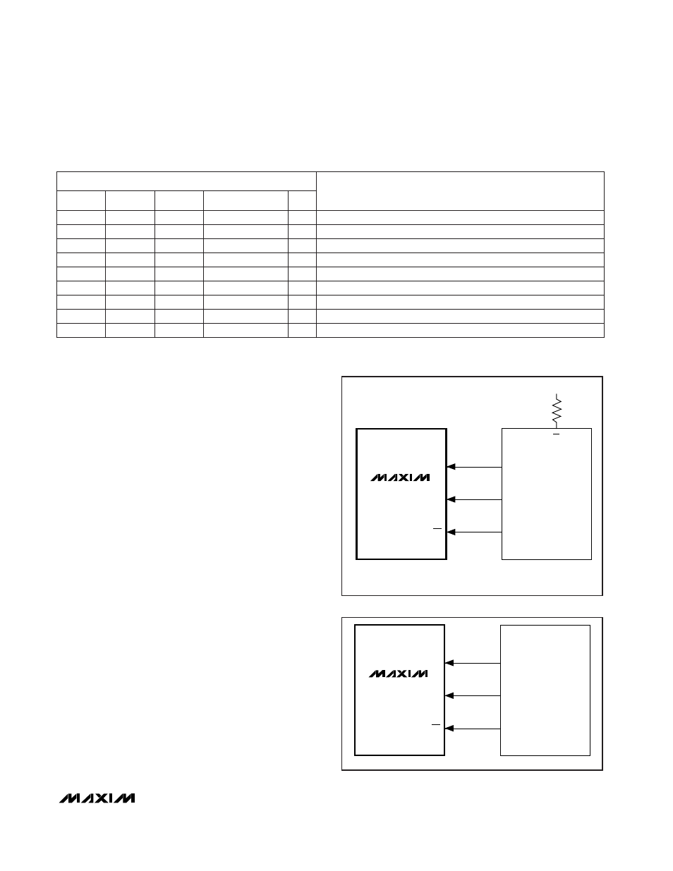
Serial-Interface Configuration
(SPI/QSPI/MICROWIRE/PIC16/PIC17)
The MAX5120/MAX5121 3-wire serial interface is com-
patible with SPI, QSPI, PIC16/PIC17 (Figure 4) and
MICROWIRE (Figure 5) interface standards. The 2-byte-
long serial input word contains three control bits, 12 data
bits in MSB-first format and one sub-bit, which is always
zero (Table 2).
The MAX5120/MAX5121’s digital inputs are double
buffered, which allows the user to:
•
Load the input register without updating the DAC
register;
•
Update the DAC register with data from the input
register;
•
Update the input and DAC registers concurrently.
MAX5120/MAX5121
+3V/+5V, 12-Bit, Serial Voltage-Output DACs
with Internal Reference
______________________________________________________________________________________
11
Load input register; DAC register unchanged.
12-Bit DAC Data
0
0
0
1
0
Update DAC register from input register; exit shutdown.
XXXXXXXXXXXX
0
1
1
1
0
Simultaneously load input and DAC registers; exit shutdown.
12-Bit DAC Data
0
UPO goes low (default).
XXXXXXXXXXXX
1
0
0
0
1
Mode 1; DOUT clocked out on SCLK’s rising edge.
1XXXXXXXXXXX
1
1
1
1
0
UPO goes high.
XXXXXXXXXXXX
1
No operation.
XXXXXXXXXXXX
0
16-BIT SERIAL WORD
Shutdown DAC (provided PDL = 1)
XXXXXXXXXXXX
1
Mode 0; DOUT clocked out on SCLK’s falling edge (default).
00XXXXXXXXXX
1
1
1
C1
C0
C2
FUNCTION
Table 1. Serial-Interface Programming Commands
X
= Don’t care
*
S0 is a sub-bit and is always zero.
DIN
SCLK
CS
MOSI
SCK
I/O
SPI/QSPI
PORT
(PIC16/PIC17)
SS
V
DD
CPOL = 0, CPHA = 0
CHE = 1, CKP = 0, SMP = 0,
SSPM3–SSPMO = 0001
( ): PIC16/PIC17 ONLY
MAX5120
MAX5121
Figure 4. SPI/QSPI Interface Connections (PIC16/PIC17)
DIN
SCLK
CS
SK
SO
I/O
MICROWIRE
PORT
MAX5120
MAX5121
Figure 5. MICROWIRE Interface Connections
D11 ............... D0
S0*
0
0
0
0
0
0
0
0
0