Rainbow Electronics MAX5121 User Manual
Page 15
Settling Time
The settling time is the amount of time required from the
start of a transition until the DAC output settles to its new
output value within the converter’s specified accuracy.
Digital Feedthrough
Digital feedthrough is noise generated on the DAC’s
output when any digital input transitions. Proper board
layout and grounding will significantly reduce this
noise, but there will always be some feedthrough
caused by the DAC itself.
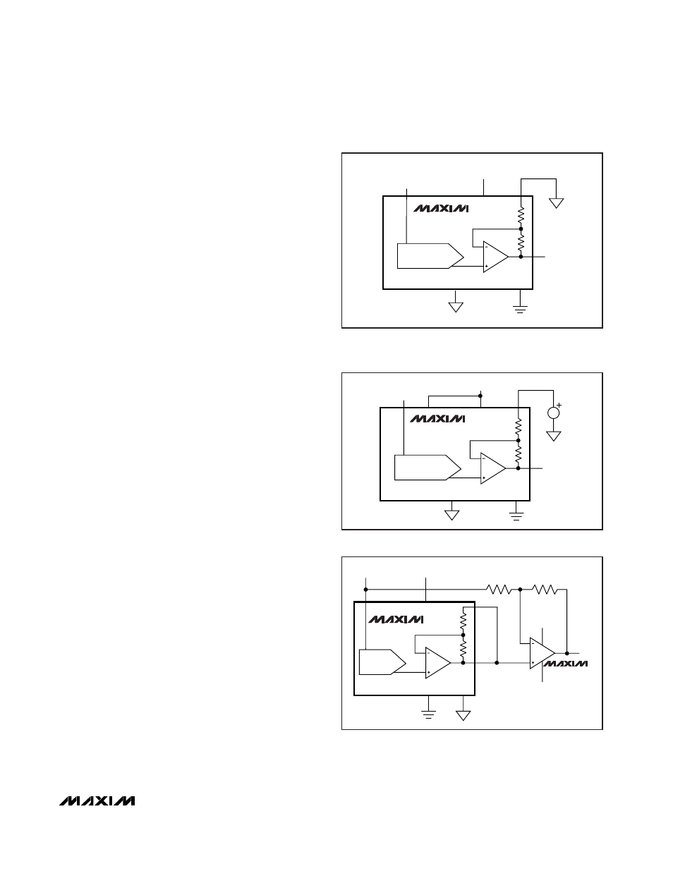
Unipolar Output
Figure 9 shows the MAX5120/MAX5121 setup for
unipolar, Rail-to-Rail
®
operation with a gain of
1.6384V/V. With its +2.5V internal reference, the
MAX5120 can generate a unipolar output range of 0V
to +4.095V. The MAX5121 produces a range of 0V to
+2.0475V with its on-board +1.25V reference. Table 5
lists example codes for unipolar output voltages. An off-
set to the output voltage can be achieved by simply
connecting the appropriate voltage to the OS pin, as
shown in Figure 10.
Bipolar Output
The MAX5120/MAX5121 can be configured for unity-
gain bipolar operation (OS = OUT) using the circuit
shown in Figure 11. The output voltage V
OUT
is thereby
given by the following equation:
V
OUT
= V
REF
·
[ {G
·
(NB / 4096)} - 1]
where NB is the numeric value of the DAC’s binary
input code, V
REF
is the voltage of the internal (or exter-
nal) precision reference, and G is the overall gain. The
application circuit in Figure 11 uses a low-cost opera-
tional amplifier (MAX4162) external to the MAX5120/
MAX5121 in a unity-gain configuration. This provides
an overall circuit gain of 2V/V. Table 6 lists example
codes for bipolar output voltages.
Reset (RSTVAL) and Clear (
CLR) Functions
The MAX5120/MAX5121 DACs offer a clear pin (CLR)
that resets the output to a certain value, depending
upon how RSTVAL is set. RSTVAL = DGND sets the
output to 0, and RSTVAL = V
DD
sets the output to mid-
scale when CLR is pulled low.
The CLR pin has a minimum input resistance of 40k
Ω
in
series with a diode to the supply voltage (V
DD
). If the
digital voltage is higher than the supply voltage for the
part, a small input current may flow, but this current will
be limited to (V
CLR
- V
DD
- 0.5V) / 40k
Ω
.
Note:
Clearing the DAC will also cause the part to exit
software shutdown (PD = 0).
MAX5120/MAX5121
+3V/+5V, 12-Bit, Serial Voltage-Output DACs
with Internal Reference
______________________________________________________________________________________
15
MAX5120
MAX5121
DAC
GAIN = 1.638V/V
REF
OUT
OS
DGND
AGND
+5V/+3V
V
DD
R
0.6384R
Figure 9. Unipolar Output Circuit (OS = AGND) Using Internal
(1.25V/2.5V) or External Reference. With external reference,
pull REFADJ to V
DD
.
MAX5120
MAX5121
DAC
AGND
DGND
REF
REFADJ
OUT
OS
V
OS
+5V/+3V
V
DD
R
0.6384R
Figure 10. Circuit for Adding Offset to the DAC’s Output
AGND
DGND
R
MAX5120
MAX5121
DAC
REF
OS
OUT
50k
50k
V-
V+
V
DD
V
OUT
+5V/+3V
0.6384R
MAX4162
Figure 11. Unity-Gain Bipolar Output Circuit Using Internal
(+1.25V/+2.5V) or External Reference. With external reference,
pull REFADJ to V
DD
.
Rail-to-Rail is a registered trademark of Nippon Motorola, Ltd.