Table 1. serial-interface programming commands – Rainbow Electronics MAX5104 User Manual
Page 7
MAX5104
Low-Power, Dual, Voltage-Output, 12-Bit DAC
with Serial Interface
_______________________________________________________________________________________
7
allowing the MAX5104 to recall the output state prior to
entering power-down when returning to normal mode.
Exit power-down by recalling the previous condition or
by updating the DAC with new information. When
returning to normal operation (exiting power-down),
wait 20µs for output stabilization.
Serial Interface
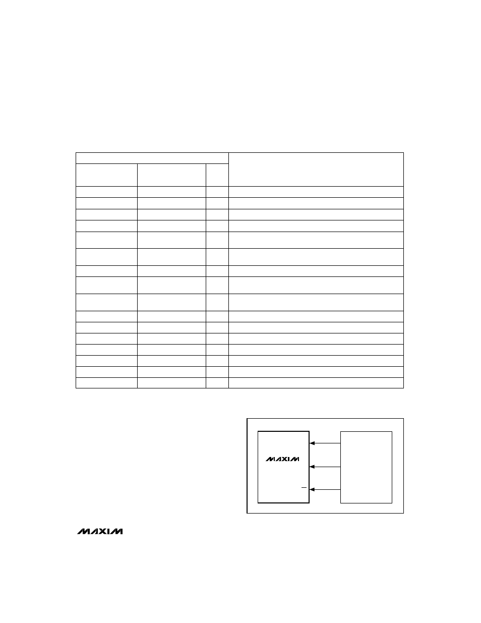
The MAX5104’s 3-wire serial interface is compatible
with both MICROWIRE (Figure 2) and SPI/QSPI (Figure 3)
serial-interface standards. The 16-bit serial input word
consists of 1 address bit, 2 control bits, 12 bits of data
(MSB to LSB), and 1 sub-bit as shown in Figure 4. The
address and control bits determine the MAX5104’s
response, as outlined in Table 1.
FUNCTION
A0
C1
C0
D11.......................D0
(MSB) (LSB)
0 0 1
12-bit DAC data
Load input register A; DAC registers are unchanged.
0 1 1
12-bit DAC data
Load all DAC registers from the shift register
(start up both DACs with new data).
1 1 0
12-bit DAC data
Load input register B; all DAC registers are updated.
0 1 0
12-bit DAC data
Load input register A; all DAC registers are updated.
1 0 1
12-bit DAC data
Load input register B; DAC registers are unchanged.
0 0 0
1 1 0 X XXXXXXXX
Power Down DAC A (provided
PDL = 1).
0 0 0
1 0 1 X XXXXXXXX
Update DAC register B from input register B
(start up DAC B with data previously stored in input register B).
0 0 0
0 0 1 X XXXXXXXX
Update DAC register A from input register A
(start up DAC A with data previously stored in input register A).
1 1 1
XXXXXXXXXXXX
Shut down both DACs (provided
PDL = 1).
1 0 0
XXXXXXXXXXXX
Update both DAC registers from their respective input registers
(start up both DACs with data previously stored in the input registers).
0 0 0
1 1 1 X XXXXXXXX
Power Down DAC B (provided
PDL = 1).
0 0 0
0 1 0 X XXXXXXXX
UPO goes low (default).
0 0 0
0 1 1 X XXXXXXXX
UPO goes high.
0 0 0
1 0 0 1 XXXXXXXX
Mode 1, DOUT clocked out on SCLK’s rising edge.
0 0 0
1 0 0 0 XXXXXXXX
Mode 0, DOUT clocked out on SCLK’s falling edge (default).
0 0 0
0 0 0 X XXXXXXXX
No operation (NOP).
Table 1. Serial-Interface Programming Commands
X = Don’t care
Note:
D11, D10, D9, and D8 become control bits when A0, C1, and C0 = 0. S0 is a sub-bit, always zero.
SCLK
DIN
CS
SK
SO
I/O
MICROWIRE
PORT
MAX5104
Figure 2. Connections for MICROWIRE
16-BIT SERIAL WORD
S0
0
0
0
0
0
0
0
0
0
0
0
0
0
0
0
0